


16-bit Timers
11-15
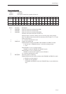
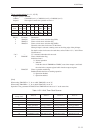
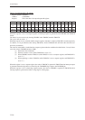
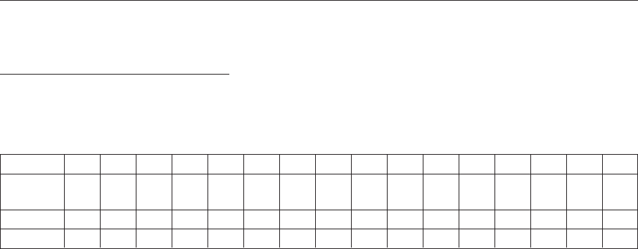
Timer 10 compare/capture A register
Register symbol: TM10CA
Address: x'340010C0
Purpose: This is the timer 10 compare/capture A register.
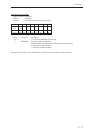
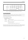
Bit No.1514131211109876543210
Bit TM10 TM10 TM10 TM10 TM10 TM10 TM10 TM10 TM10 TM10 TM10 TM10 TM10 TM10 TM10 TM10
name CA15 CA14 CA13 CA12 CA11 CA10 CA9 CA8 CA7 CA6 CA5 CA4 CA3 CA2 CA1 CA0
Reset 0 0 0 0 0 0 0 0 0 0 0 0 0 0 0 0
Access R/W R/W R/W R/W R/W R/W R/W R/W R/W R/W R/W R/W R/W R/W R/W R/W
When this register is set as a compare register, an interrupt request is generated when TM10BC and TM10CA
match.
The timer 10 cycle can be set by clearing TM10BC when TM10BC matches TM10CA.
The cycle is the set value + 1.
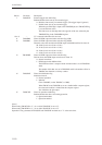
When this register is set as a double-buffer compare register, data that is written to TM10CA is stored temporarily
in a buffer, so it is possible that after writing TM10CA, a read of TM10CA will still return the value that was
previously stored there.
The value set in the buffer is loaded into the compare register under the conditions described below. In any of these
cases, the value in TM10BC becomes x'0000.
(1) When timer 10 is initialized
(2) When an overflow occurs (while TM10CAE is set to "0")
(3) When TM10BC matches TM10CA (while TM10CAE is set to "1")
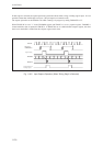
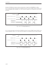
When this register is set as a capture register, the value in TM10BC is captured in TM10CA and an interrupt request
is generated when the edge that was selected by the TM10AEG flag is input to the TM10IOA pin.
When this register is set as a dual-edge capture register, the value in TM10BC is captured in TM10CA and an
interrupt request is generated at either a rising edge or a falling edge.