


Interrupt Controller
9-8
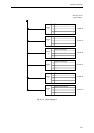
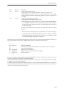
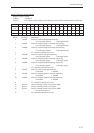
Group n interrupt control register GnICR (n = 2 to 19)
Registers G2ICR to G19ICR control level interrupts for groups 2 to 19, respectively.
Each register confirms the group interrupt level as well as the enabling, request, and detection of interrupts within
the respective group.
The explanation on this page applies to registers G2ICR to G19ICR.
The interrupt control registers for group 2 to 19 are described starting on page 9-10.
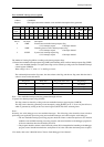
Bit No. 15 14 13 12 11 10 9876543210
Bit
- LV2 LV1 LV0 IE3 IE2 IE1 IE0 IR3 IR2 IR1 IR0 ID3 ID2 ID1 ID0
name
Reset 0000000000000000
Access R R/W R/W R/W R/W R/W R/W R/W R/W R/W R/W R/W R/W R/W R/W R/W
Bit No. Bit name Description
3 to 0 ID3 to 0 Group n interrupt detection register
• This register stores the logical product of the IEn(n=3 to 0) and IRn(n=3 to 0)
bits.
• If an interrupt that is enabled in the IEn bits is generated, the bit corresponding to
the interrupt is "1".
7 to 4 IR3 to 0 Group n interrupt request register
• This register stores interrupt requests. Each bit corresponds to an interrupt.
• After receiving the interrupt, these bits are cleared by software in the interrupt
processing program.
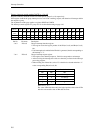
• When clearing one of these bits, write a "0" to the bit to be cleared and write a "1"
to the corresponding IDn(n=3 to 0) bit.
Write data Result of write
IRn IDn IRn
0 0 No change
1 0 No change
01 0
11 1
Note: n= 0, 1, 2, 3
The value of IDn after the write is the logical product of the value of IEn
after the write and the value of IRn after the write.