


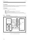
I/O Ports
15-60
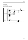
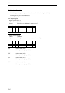
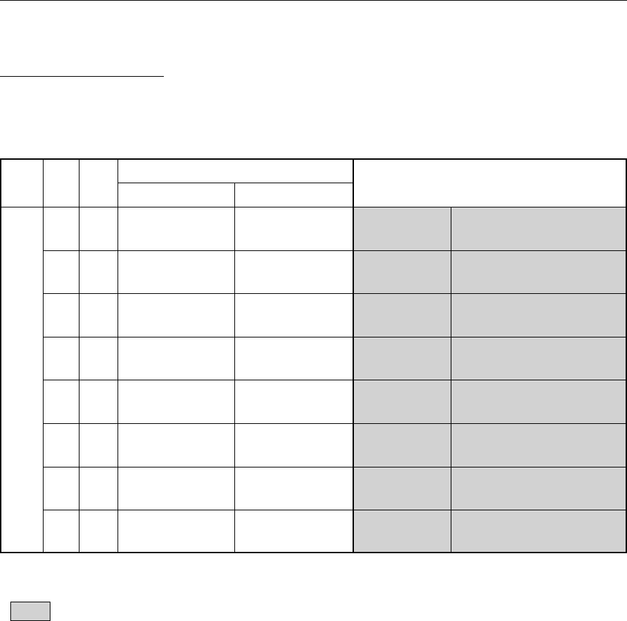
15.13.3 Pin Configurations
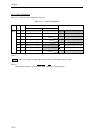
Table 15-13-1 shows the pin configurations for port B.
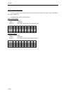
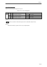
Table 15-13-1 Port B Configuration
Port Pin PBn PBM = "1" PBM = "0"
No. PBnD = "1" PBnD = "0"
Port B 14 PB0 General-purpose General-purpose A8 Address output
output port input port <ADM8>> *
1
<<Address/data input/output>>
13 PB1 General-purpose General-purpose A9 Address output
output port input port <<ADM9>> *
1
<<Address/data input/output>>
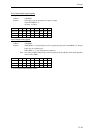
12 PB2 General-purpose General-purpose A10 Address output
output port input port <<ADM10>> *
1
<<Address/data input/output>>
11 PB3 General-purpose General-purpose A11 Address output
output port input port <<ADM11>> *
1
<<Address/data input/output>>
10 PB4 General-purpose General-purpose A12 Address output
output port input port <<ADM12>> *
1
<<Address/data input/output>>
8 PB5 General-purpose General-purpose A13 Address output
output port input port <<ADM13>> *
1
<<Address/data input/output>>
7 PB6 General-purpose General-purpose A14 Address output
output port input port <<ADM14>> *
1
<<Address/data input/output>>
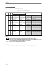
6 PB7 General-purpose General-purpose A15 Address output
output port input port <<ADM15>> *
1
<<Address/data input/output>>
[Note 1]
: When reset (whether in address/data separate mode or address/data multiplex mode)
*1 : In the event of a reset in address/data multiplex mode, the PBPU bit in the PBMD register is set to
"1" and the address/data pins (the 8 bits ADM[15:8]) are pulled up.
<<>> : These pins are set in address/data multiplex mode.
[Note 2]
When the bus authority is granted, A15 to A8 (ADM15 to ADM8) go to high impedance.