


16-bit Timers
11-32
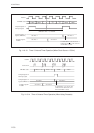
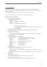
Once the counting operation is enabled, TM10BC is incremented each time that the specified edge is input to the
TM10IOB pin. Once (value in compare/capture A register + 1) edges are counted, TM10BC is cleared and a
compare/capture A register interrupt request is generated.
If the value in the TM10CA register is changed while the counting operation is in progress, the value in the buffer
is loaded into the compare register the next time that TM10BC is cleared, and the interrupt cycle is then changed. If
the interrupt cycle will be changed while the counting operation is in progress, set TM10CA as a double-buffer
compare register.
■ Procedure for ending operation
(1) Stop the timer counting operation.
Set TM10CNE to "0" in the TM10MD register, stopping the counting operation.
(2) Initialize the timer, if necessary.
If TM10LDE is set to "1" in the TM10MD register, TM10BC is cleared and the timer output is reset. If the
TM10CA register is set as a double-buffer, the value in the compare register buffer is loaded into the
compare register.
If TM10LDE is not set to "1" after the timer is stopped, the binary counter, the compare register and the pin
output are maintained as they were before the timer was stopped. If TM10CNE is set to "1" again, the
count resumes from the state that was in effect immediately before the timer was stopped.
[Note]
The pin input is sampled according to IOCLK. Input a signal with a pulse width of at least 6, 3, or 1.5 SYSCLK
cycles when (MCLK frequency/SYSCLK frequency) = 1, 2, or 4, respectively.
Also note that event counting is not possible when IOCLK is stopped (in HALT or STOP mode).
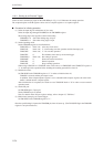
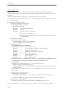
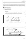
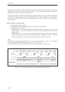
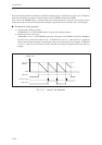
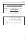
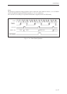
Fig. 11-6-15 Event Count Operation (When “Rising Edge” is Selected)
IOCLK
Pin input
(TM10IOB)
x'0000 x'0001TM10CA valueTM10CA value-1
Count clock
TM10BC value
Compare/capture A
interrupt request