


2-15
CPU
0ID
15
0
1413121110987654321
000000 00000
0ID
15
0
1413121110987654321
LV IE IR
G0ICR (NMICR)
GnICR (n = 2 to 19)
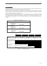
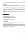
2.5.2 Registers
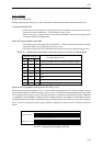
[Flags in the PSW] (CPU)
Interrupt-related flags in the processor status word (PSW) include interrupt enable and interrupt mask level.
IE (Interrupt Enable) R/W
• This flag allows all interrupts to be accepted except for non-maskable interrupts and reset interrupts.
Interrupts are allowed when IE = 1. IE = 0 when the system is reset.
• When an interrupt is accepted, IE is cleared (interrupt prohibited). Set IE when accepting nested
interrupts within the interrupt handler.
IM2 to IM0 (Interrupt Mask Level) R/W
• This holds the current interrupt mask level. When IE = 1, CPU accepts interrupts with levels higher
than IM2 to IM0. Level 0 (000) when the system is reset.
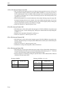
• The following table shows the relationship between mask levels and acceptable interrupt levels.
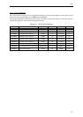
Table 2-5-1 Relationship between Mask Levels and Interrupt Levels that Can Be Accepted
Interrupt mask level
IM2 IM1 IM0
Acceptable interrupt level
000
Interrupt prohibited (only non-maskable interrupts accepted)
0010
0100-1
0110-2
1000-3
1010-4
1100-5
1110-6
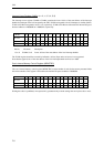
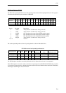
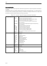
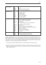
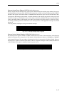
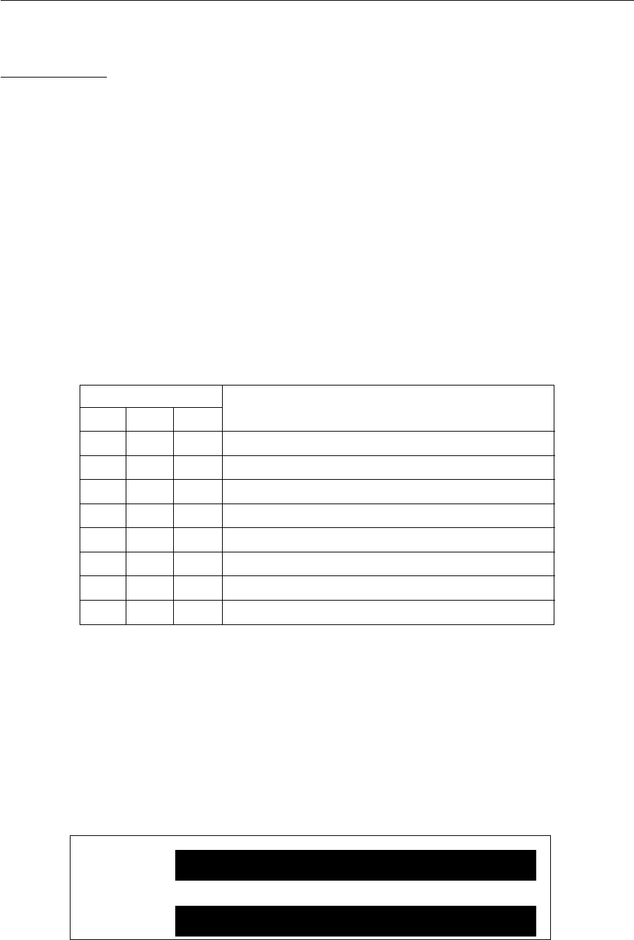
[Interrupt Control Registers (GnICR)] R/W halfword/byte access
Interrupt control registers (GnICR: n = 0, 2 to 19) combine interrupt priority level, interrupt enable, interrupt
request and interrupt detect fields into a single register in order to control CPU external peripheral interrupts. There
are 19 interrupt control registers, one for each group, and they are located in the internal I/O space from x'34000100
to x'3400014C. Register G0ICR is dedicated for non-maskable interrupts, and G0ICR is called NMICR (from the
least significant bit: external pin non-maskable interrupt, watchdog timer overflow interrupt, system error interrupt).
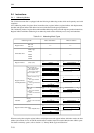
Fig. 2-5-2 shows the interrupt control register (GnICR) configuration, and each field is described in detail as
follows.
Fig. 2-5-2 Interrupt Control Register (GnICR)