


Serial Interface
13-16
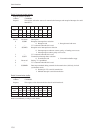
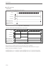
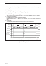
■ UART mode timing
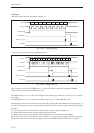
<Transmission>
• Transfer with 8-bit data length, parity on, and 1 stop bit
Fig. 13-2-9 Timing Chart (6)
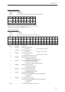
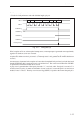
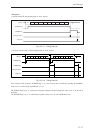
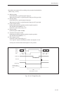
• Two-byte transfer with 7-bit data length, parity on, and 1 stop bit
Fig. 13-2-10 Timing Chart (7)
When transmission is enabled, transmission starts when data is written to SC0TXB.
Continuous transmission is possible by writing data to SC0TXB again while transmission is in progress.
During a 7-bit transfer, the MSB (bit 7) is ignored.
The SC0TXF flag is set to "1" when data is written to SC0TXB, and is set to "0" at the end of transmission.
The SC0TBF flag is set to "1" when data is written to SC0TXB, and is set to "0" at the start of transmission.
SBO pin
Data write
SC0TXF flag
SC0TBF flag
Interrupt request (when
set to “transmission buffer
empty”)
Interrupt request (when
set to “transmission end”)
bp1 bp2 bp3 bp4 bp5 bp6 bp7 PTYbp0ST SP
SBO pin
Data write
SC0TXF flag
SC0TBF flag
Interrupt request (when
set to “transmission buffer
empty”)
Interrupt request (when
set to “transmission end”)
bp1 bp2 bp3 bp4 bp5 bp6bp0ST SP bp1 bp2 bp3 bp4 bp5 bp6bp0ST SPPTY PTY