


16-bit Timers
11-10
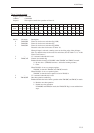
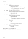
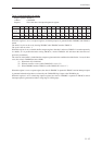
Bit No. Bit name Description
7 TM10TGE External trigger start enable flag
Enables/disables timer start by an external trigger.
0: Disables timer start by an external trigger. (The trigger input is ignored.)
1: Enables timer start by an external trigger.
When the specified edge is input to the TM10IOB pin, the TM10CNE flag
is set and the timer starts.
The timer starts on the edge that is the opposite of the one selected by the
TM10BEG flag in the TM10MDB register.
10 to 8 — "0" is returned when these bits are read.
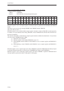
11 TM10PM0 Timer 10 PWM output resolution selection flag (LSB)
12 TM10PM1 Timer 10 PWM output resolution selection flag (MSB)
These bits select the resolution for PWM output with additional bits for timer 10.
00:10 bits (basic wave 8 bits + 2 bits)
01:11 bits (basic wave 8 bits + 3 bits)
10:12 bits (basic wave 8 bits + 4 bits)
11:14 bits (basic wave 8 bits + 6 bits)
13 TM10PME Timer 10 PWM output waveform selection flag
This bit selects the PWM output waveform for timer 10.
0: Normal waveform
1: PWM output with additional bits
The PWM waveform is output with the resolution that is set in TM10PM1
and 0.
The number of bits that was set in TM10PM1 and 0 is the number of bits in
TM10BC that function as a binary counter.
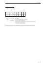
14 TM10LDE Timer 10 initialization flag
Initializes timer 10.
0: Normal operation
1: Initialize
Clears TM10BC (so that TM10BC = x'0000).
When TM10CA and TM10CB are set as a double-buffer compare register,
the value in the buffers is loaded into the compare register.
Also initializes the pin output.
15 TM10CNE Timer 10 operation enable flag
Enables/disables the timer 10 counting operation.
0: Operation disabled.
1: Operation enabled.
[Note]
When setting TM10CNE to "1", do so while TM10LDE is set to "0".
When setting TM10LDE to "1", do so while TM10CNE is set to "0".
Operation is not guaranteed if TM10CNE and TM10LDE are both set to "1" at the same time.