


1-8
General Specifications
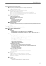
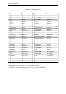
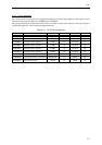
Table 1-4-2 Pin Function Table (2/2)
Category Pin name
Input/ Number
Pin Function
Output of pins
Reset RST I 1 Reset input
Interrupts NMIRQ I 1 External non-maskable interrupt input
IRQ7 to 0 I 8 External interrupt 7 to 0 inputs (multipurpose)
Serial interface SBI3 to 0 I 4 Serial 3 to 0 data inputs (multipurpose)
SBO3 to 0 I/O 4 Serial 3 to 0 data inputs/outputs (multipurpose)
(SBO3 is output only.)
SBT3 to 0 I/O 4
Serial 3 to 0 transfer clock inputs/outputs (multipurpose)
(SBT3 is input only.)
8-bit timer TM7IO to I/O (8) PWM output/Toggle output/shared by event count
TM0IO input
16-bit timer TM10IOA I/O (1) PWM output/capture input (multipurpose of IRQ2 )
TM10IOB I/O (1) PWM output/capture input (multipurpose of IRQ3)
TM13IO to I/O (3) Dual use for event count/toggle output
TM11IO
A/D converter VREFH I 1 A/D converter reference voltage input
(Use input of AVDD to 0 V only.)
ADTRG I (1) A/D converter trigger conversion input (multipurpose
of IRQ3)
AN3 to 0 I (4) A/D converter analog signal inputs (multipurpose of
IRQ7 to 4) (Use input of VREFH to 0 V only.)
AVDD 1 Analog system power supply (+3.3 V)
AVSS 1 Analog system GND
I/O ports P02 to P00 O (3) Port 0; output port (multipurpose)
P17 to P10 I/O (8) Port 1; input/output port (multipurpose)
P27 to P20 I/O (8) Port 2; input/output port (multipurpose)
P30 I/O (1) Port 3; input/output port (multipurpose)
P45 to P40 I/O (6) Port 4; input/output port (multipurpose)
P55 to P50 I/O (6) Port 5; input/output port (multipurpose)
P63 to P60 I/O (4) Port 6; input/output port (multipurpose)
P73 to P70 O (4) Port 7; output port (multipurpose)
P83 to P80 I (4) Port 8; input port (multipurpose)
P96, P95, P91, P90
I/O (4) Port 96, 95, 91, 90; input/output port (multipurpose)
P97, P94 to P92
O (4) Port 97, 94, 93, 92; output port (multipurpose)
PA7 to PA0 I/O (8) Port A; input/output port (multipurpose)
PB7 to PB0 I/O (8) Port B; input/output port (multipurpose)
PC3 to PC0 O (4) Port C; output port (multipurpose)
Notes:
1. A number that is not enclosed in parentheses in the “Number of pins” column indicates the main pins, while a
number enclosed in parentheses indicates multipurpose pins.
2. After the reset condition is released, maintain the NMIRQ pin at the high level until the initialization routine
(which sets the stack pointer SP) is completed. If the NMIRQ pin is not used, connect it to VDD via a resistor.