


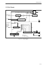


Watchdog Timer
12-5
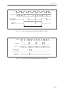
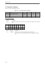
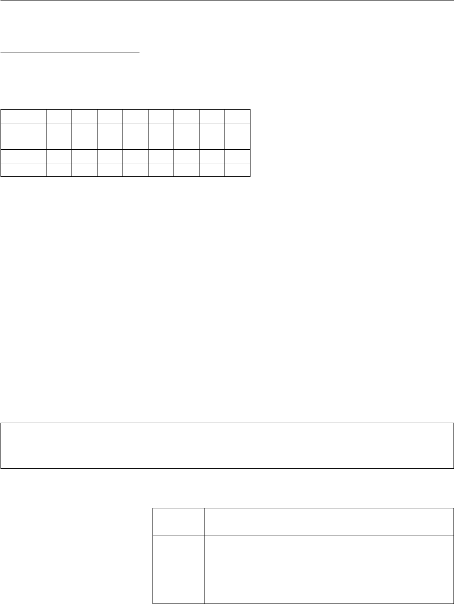
Watchdog timer control register
Register symbol: WDCTR
Address: x'34004008
Purpose: This register sets the watchdog timer operation control conditions.
Bit No. 7 6 543210
Bit WD WD WD WD
-
WD WD WD
name CNE RST OVT OVF CK2 CK1 CK0
Reset 0 0 000001
Access R/W R/W R/W R R R/W R/W R/W
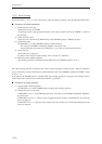
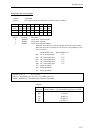
Bit No. Bit name Description
0 WDCK0 Clock source selection (LSB)
1 WDCK1 Clock source selection
2 WDCK2 Clock source selection (MSB)
These bits select the clock source for the high-order 8 bits of the counter.
When the reset state is released, the clock source corresponding to "001"
below is selected.
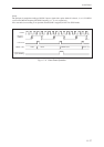
When CKSEL is "H" When CKSEL is "L"
000: 1/2
8
of the OSCI input 1/2
9
001: 1/2
10
of the OSCI input 1/2
11
010: 1/2
12
of the OSCI input 1/2
13
011: 1/2
14
of the OSCI input 1/2
15
100: 1/2
16
of the OSCI input 1/2
17
101: Setting prohibited
110: Setting prohibited
111: Setting prohibited
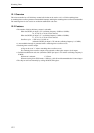
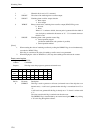
Overflow cycle = 2
(n + WDCK x 2)
/(f x 10
3
) [ms]
Where, n = 16 (CKSEL pin is “H”) or n = 17 (CKSEL pin is “L”);
WDCK = WDCK[2:0]; f: Oscillation input frequency [unit: MHz]
Example
Selection
Overflow cycle
When CKSEL is "H" and oscillating frequency is 15 MHz
000 4.369 ms
001 17.476 ms
010 69.905 ms
011 279.620 ms
100 1118.481 ms