


Serial Interface
13-27
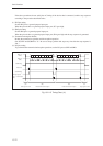
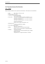
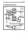
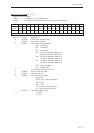
Serial n control register (n = 1, 2)
Register symbol: SCnCTR
Address: x'34000810 (n =1), x'34000820 (n =2)
Purpose: This register sets the serial interface n operation control conditions.
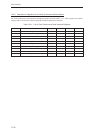
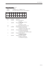
Bit No.1514131211109876543210
Bit SCn SCn – – – SCn SCn SCn SCn SCn SCn SCn – SCn SCn SCn
name TXE RXE MD0 OD TOE CLN PB2 PB1 PB0 CK2 CK1 CK0
Reset 0 0 0 0 0 0 0 0 0 0 0 0 0 0 0 0
Access R/W R/W R R R R/W R/W R/W R/W R/W R/W R/W R R/W R/W R/W
Bit No. Bit name Description
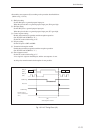
0 SCnCK0 Clock source selection (LSB)
1 SCnCK1 Clock source selection
2 SCnCK2 Clock source selection (MSB)
000: 1/2 IOCLK
001: 1/8 IOCLK
010: 1/32 IOCLK
011: 1/2 timer 8 underflow (When n=1)
1/2 timer 9 underflow (When n=2)
100: 1/8 timer 2 underflow (When n=1)
1/8 timer 3 underflow (When n=2)
101: 1/8 timer 8 underflow (When n=1)
1/8 timer 9 underflow (When n=2)
110: Setting prohibited
111: External clock
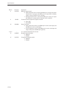
3 — "0" is returned when this bit is read.
4 SCnPB0 Parity bit selection (LSB)
5 SCnPB1 Parity bit selection
6 SCnPB2 Parity bit selection (MSB)
000: None
001, 010, 011: Setting prohibited
100: 0 fixed
101: 1 fixed
110: Even (even number of ones)
111: Odd (odd number of ones)
7 SCnCLN Character length selection
0: 7 bits
1: 8 bits