


16-bit Timers
11-12
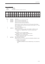
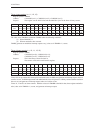
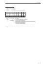
Timer n base register (n = 11, 12, 13)
Register symbol: TMnBR
Address: x'34001092 (n=11), x'34001094 (n=12), x'34001096 (n=13)
Purpose: This register sets the initial value and the underflow cycle for the timer n binary counter.
Bit No.1514131211109876543210
Bit TMn TMn TMn TMn TMn TMn TMn TMn TMn TMn TMn TMn TMn TMn TMn TMn
name BR15 BR14 BR13 BR12 BR11 BR10 BR9 BR8 BR7 BR6 BR5 BR4 BR3 BR2 BR1 BR0
Reset 0 0 0 0 0 0 0 0 0 0 0 0 0 0 0 0
Access R/W R/W R/W R/W R/W R/W R/W R/W R/W R/W R/W R/W R/W R/W R/W R/W
The value set in TMnBR is loaded into TMnBC under the following conditions:
(1) When TMnLDE = 1
(2) When an underflow has occurred.
TMnBC generates an underflow interrupt request every (value set in TMnBR + 1) counts.
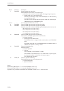
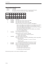
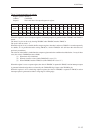
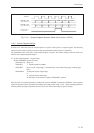
Timer n binary counter (n = 10, 11, 12, 13)
Register symbol: TMnBC
Address: x'340010A0 (n=10), x'340010A2 (n=11),
x'340010A4 (n=12), x'340010A6 (n=13)
Purpose: This is the binary counter for timer n.
The counter value can be read from this register.
Bit No.1514131211109876543210
Bit TMn TMn TMn TMn TMn TMn TMn TMn TMn TMn TMn TMn TMn TMn TMn TMn
name BC15 BC14 BC13 BC12 BC11 BC10 BC9 BC8 BC7 BC6 BC5 BC4 BC3 BC2 BC1 BC0
Reset 0 0 0 0 0 0 0 0 0 0 0 0 0 0 0 0
Access R R R R R R R R R R R R R R R R
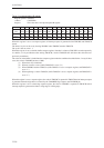
Timer 10 is an up-counter that counts up from an initial value of x'0000, and generates an interrupt request when an
overflow occurs. In PWM output mode with additional bits, timer 10 operates as a binary counter with the resolution
that was set, and generates an interrupt request when an overflow occurs.
Timers 11, 12 and 13 are down-counters. With the value set in TMnBR as the initial value, these registers underflow
after (value set in TMnBR + 1) counts, and generate an interrupt request.