


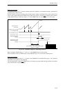


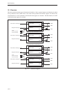

Serial Interface
13-7
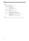
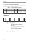
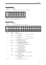
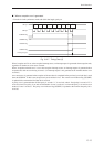
6 SC0PB2 Parity bit selection (MSB)
000: None
001, 010, 011: Setting prohibited
100: 0 fixed
101: 1 fixed
110: Even (even number of ones)
111: Odd (odd number of ones)
7 SC0CLN Character length selection
0: 7 bits
1: 8 bits
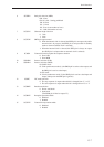
8 SC0TOE SBT0 pin output control
0: When the internal clock is selected, the SBT0 pin is an output only while
transmission is in progress (the SBT0 pin is an input when in standby
mode or when an external clock is selected)
1: When the internal clock is selected, the SBT0 pin is always an output
(the SBT0 pin is an input when an external clock is selected)
9 SC0OD Transmission and reception bit sequence selection
0: From LSB
1: From MSB
10 SC0MD0 Protocol selection (LSB)
11 SC0MD1 Protocol selection (MSB)
00:UART mode
01: Clock synchronous mode (1) (the SBO0 pin is used as a data output, and
the SBI0 pin is used as a data input)
10:I2C mode
11:Clock synchronous mode (2) (the SBO0 pin is used as a data input and
output, and input on the SBI0 pin is ignored)
12 SC0IIC I2C mode selection
0: The stop sequence is output when this bit is changed from "1" to "0"
1: The start sequence is output when this bit is changed from "0" to "1"
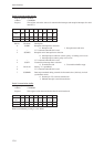
13 SC0BKE Break transmission
0: Do not send break
1: Send break
(The SBO0 pin is fixed to output "0".)
14 SC0RXE Reception operation enable
0: Disabled
1: Enabled
15 SC0TXE Transmission operation enable
0: Disabled
1: Enabled