


Serial Interface
13-21
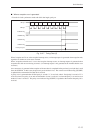
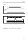
• Perform data transmission/reception (B) according to the procedure described below:
(1) Ack setting
"Ack" is represented by the parity bits.
Set the parity bit selection flags (SC0PB2 to 0) to "1 fixed" or "0 fixed" in accordance with the communications
protocol for the device that is connected. (When sending "Ack", set "0 fixed"; when sending NO-Ack, set "1
fixed ".)
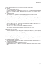
(2) Transmission/reception
When transmitting, write the data that is to be transmitted in the transmission buffer (SC0TXB).
When receiving, write "x'FF" in the transmission buffer (SC0TXB).
After the buffers are written, the clock signal is output and the transmission/reception operation is performed.
After transmission/reception are completed, the low signal output is maintained on the SBT and SBO pins.
(3) Reading the reception buffer
Always be certain to read the reception buffer after the transmission/reception operation is completed.
(It is necessary to read the reception buffer after a transmission operation.)
(4) Ack confirmation
Ack can be read as a parity error. Read the parity error indication flag (SC0PEF). When parity is set to "0
fixed", the value of SC0PEF is the value of Ack.
When parity is set to "1 fixed", the inverted value of SC0PEF is the value of Ack.
When performing consecutive transmission/reception operations, repeat steps (1) to (4).
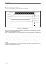
•
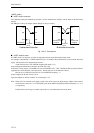
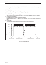
Wait function under SCL control
The transmission/reception operation waits until SCL is released if SCL is driven low by a device performing
slave transmission/reception. In this case, SCL goes high for 1/2 the normal interval (1/4 the one-bit width
specified by the clock source selection flags (SC0CK2 to 0)).
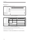
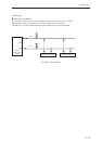
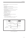
• Send the stop sequence (C) according to the procedure described below:
(1) Sending stop sequence
When the I2C mode selection flag (SC0IIC) is changed from "1" to "0", the SBT pin goes high. One IOCLK
cycle after the SBT pin goes high, the SBO pin goes high and the stop sequence is sent.
(2) Confirmation of sending stop sequence
If the stop sequence was generated normally, the I2C stop sequence detection flag (SC0SPF) changes to "1".
(3) Transmission/reception disable
Disable the transmission operation and the reception operation.
(Set SC0TXE and SC0RXE to "0". Be sure to always perform this step every time after the stop sequence is
sent.)