


Serial Interface
13-12
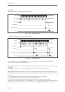
<Reception>
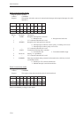
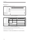
• One-byte transfer with 8-bit data length and parity on
Fig. 13-2-5 Timing Chart (3)
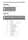
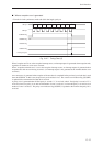
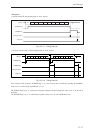
• Two-byte transfer with 8-bit data length and parity off
Fig. 13-2-6 Timing Chart (4)
After reception end (when the SC0RBF flag is "1"), the received data is fetched by reading the SC0RXB.
In the case of a 7-bit transfer, the MSB (bit 7) is "0".
The SC0RXF flag is set to "1" at the start of reception (at the falling edge of SBT pin ), and is set to "0" at the end
of reception.
The SC0RBF flag is set to "1" at the end of reception, and is set to "0" when SC0RXB is read.
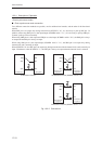
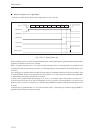
Sending dummy data makes it possible to receive data while supplying the clock from the microcomputer side. In
this case, interrupt requests are also generated by the transmission source. Receive data according to the following
procedure:
(1) Select the internal clock as the reference clock, and set the parity, character length, etc.
(2) Enable both the transmission operation and the receiving operation.
(3) When dummy data is written to the transmission buffer, the clock is sent and reception begins.
When using clock synchronous mode (2), set the SBO pin as a general-purpose input port before writing the
dummy data to the transmission buffer, and then reset the pin as the SBO pin after transmission is complete.
bp1 bp2 bp3 bp4 bp5 bp6bp0
SBI pin
SBT pin
Interrupt request
SC0RXF flag
SC0RBF flag
Data read
bp1 bp2 bp3 bp4 bp5 bp6bp0 bp7bp7
bp1 bp2 bp3 bp4 bp5 bp6 bp7bp0
SBI pin
SBT pin
Interrupt request
SC0RXF flag
SC0RBF flag
Data read
PTY