


Interrupt Controller
9-9
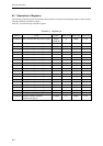
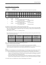
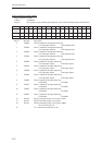
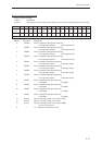
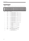
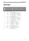
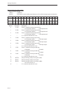
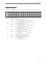
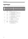
Bit No. Bit name Description
11 to 8 IE3 to 0 Group n interrupt enable register
• This register is used to specify whether an interrupt is enabled or not.
• When an IEn(n=3 to 0) bit is set to "1", the corresponding interrupt is enabled.
• Setting an IEn bit while the corresponding IRn(n=3 to 0) bit is set generates an
interrupt.
14 to 12 LV2 to 0 Group n interrupt priority level register
• This register sets the interrupt priority levels.
• If the interrupt priority level set in the LV2 to 0 bits is smaller than the IM2 to 0
bits in the PSW, interrupts of the corresponding interrupt group are possible.
Interrupts in the same interrupt group are all of the interrupt priority level specified
by the LV2 to 0 bits.
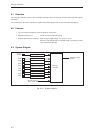
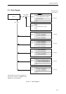
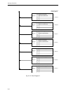
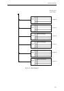
For details on the interrupt factor assigned to each group, refer section 9.4, "Block
Diagram."
• When simultaneous interrupt requests are generated from more than one interrupt
group, the interrupt with the highest interrupt priority level is accepted. In addition,
if multiple interrupt priority levels are set in the same level, the interrupt from the
group with the smallest group number is accepted.
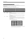
Perform operations concerning the interrupt priority level bits (LV2 to 0) and the interrupt enable bits (IE3 to 0) in
the group n interrupt control register (GnICR) while interrupts are disabled, as shown below.
...................
and 0xf7ff, psw ; Clears IE in the PSW.
nop ; Insert in order to guarantee that GnICR is accessed after IE has been definitely
nop ; cleared in pipeline fashion.
mov d0, (GnICR) ; Change LV2 to 0 and IE3 to 0.
mov (GnICR), d0 ; Insert in order to synchronize with the store buffer.
or 0x0800, psw ; Set IE in the PSW.
...................
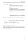
However, while the interrupt handler is running, IE in the PSW is "0," unless IE has been set. Therefore, it is not
necessary to explicitly clear the IE bit and disable interrupts.
The nop instructions indicated above can be any instructions, as long as they do not change the IE bit in the PSW,
or change LV2 to 0 or IE3 to 0 in GnICR.
In addition, the reason for inserting two nop instructions is to ensure that the minimum number of cycles needed to
change the IE bit in the PSW are provided; therefore, any instruction that consumes at least the same number of
cycles as two nop instructions may be inserted.