


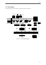

2-6
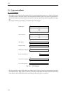
CPU
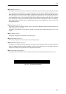
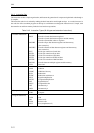
Z: Zero Flag
This flag is set when an operation result is all zeroes, and is cleared by any other result. This flag is
also cleared by a reset.
N: Negative Flag
This flag is set if the MSB of an operation result is "1", and is cleared if the MSB is "0". This flag
is also cleared by a reset.
C: Carry Flag
This flag is set when a carry or borrow to or from the MSB is generated in the course of executing an
operation, and is cleared if no carry or borrow is generated. This flag is also cleared by a reset.
V: Overflow Flag
This flag is set when an overflow occurs in a signed value in the course of executing an operation,
and is cleared if no overflow is generated. This flag is also cleared by a reset.
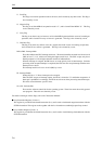
IM2 to IM0: Interrupt Mask
These bits indicate the CPU interrupt mask level. The three bits define the mask level from level 0
(000) to level 7 (111), with level 0 being the highest mask level. The CPU accepts only those
interrupt requests of a level higher than the mask level indicated here.
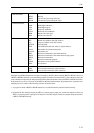
When an interrupt is accepted, the IM bits are set to the priority level of that interrupt. Until the
processing of the accepted interrupt is completed, the CPU does not accept interrupts with the same
interrupt level or lower.
The interrupt mask level is set to level 0 (000) by a reset.
IE: Interrupt Enable
Setting this bit to “1” allows interrupts to be accepted.
Once the CPU accepts an interrupt request, the IE bit is cleared to "0" and further acceptance of
interrupts is prohibited. Accordingly, the IE bit must be reset when processing nested interrupts.
This bit is cleared when the system is reset.
S1 to S0: Software Bits
These are the software control bits for the operating system. These bits cannot be used by general
user programs. These bits are cleared by a reset.
For details on changes of these flags, refer to the "Instruction Manual".
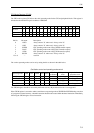
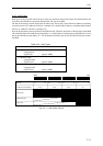
■ Loop Instruction Register (32-bit x 1)
This register is provided for the branch instruction (Lcc), and is used to load branch target instructions with the
SETLB instruction. This register works together with the Lcc instruction to enable high-speed loop control.
■ Loop Address Register (32-bit x 1)
This register is provided for the branch instruction (Lcc), and is used to load following fetch addresses with the
SETLB instruction.