


Using 802.1s Multiple Spanning Tree MST General Overview
OmniSwitch 6600 Family Network Configuration Guide April 2006 page 6-7
Comparing MSTP with STP and RSTP
Using MSTP (802.1s) has the following items in common with STP (802.1D) and RSTP (802.1w) proto-
cols:
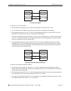
• Each protocol ensures one data path between any two switches within the network topology. This
prevents network loops from occurring while at the same time allowing for redundant path configura-
tion.
• Each protocol provides automatic reconfiguration of the network Spanning Tree topology in the event
of a connection failure and/or when a switch is added to or removed from the network.
• All three protocols are supported in the flat Spanning Tree operating mode.
• The flat mode CST instance automatically determines port states and roles across VLAN port and
MSTI associations. This is because the CST instance is active on all ports and only one BPDU is used
to forward information for all MSTIs.
• MSTP is based on RSTP.
Using MSTP differs from STP and RSTP as follows:
• MSTP is only supported when the switch is running in the flat Spanning Tree mode. STP and RSTP
are supported in both the 1x1 and flat modes.
• MSTP allows for the configuration of up to 16 Multiple Spanning Tree Instances (MSTI) in addition to
the CST instance. Flat mode STP and RSTP protocols only use the single CST instance for the entire
switch. See “What is a Multiple Spanning Tree Instance (MSTI)” on page 6-7 for more information.
• MSTP applies a single Spanning Tree instance to an MSTI ID number that represents a set of VLANs;
a one to many association. STP and RSTP in the flat mode apply one Spanning Tree instance to all
VLANs; a one to all association. STP and RSTP in the 1x1 mode apply a single Spanning Tree
instance to each existing VLAN; a one to one association.
• The port priority and path cost parameters are configurable for an individual MSTI that represents the
VLAN associated with the port.
• The flat mode 802.1D or 802.1w CST is identified as instance 1. When using MSTP, the CST is identi-
fied as CIST (Common and Internal Spanning Tree) instance 0. See “What is the Common and Inter-
nal Spanning Tree Instance” on page 6-9 for more information.
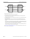
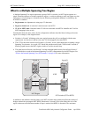
• MSTP allows the segmentation of switches within the network into MST regions. Each region is seen
as a single virtual bridge to the rest of the network, even though multiple switches may belong to the
one region. See “What is a Multiple Spanning Tree Region” on page 6-8 for more information.
• MSTP has lower overhead than a 1x1 configuration. In 1x1 mode, because each VLAN is assigned a
separate Spanning Tree instance, BPDUs are forwarded on the network for each VLAN. MSTP only
forwards one BPDU for the CST that contains information for all configured MSTI on the switch.
What is a Multiple Spanning Tree Instance (MSTI)
An MSTI is a single Spanning Tree instance that represents a group of VLANs. Alcatel switches support
up to 16 MSTIs on one switch. This number is in addition to the Common and Internal Spanning Tree
(CIST) instance 0, which is also known as MSTI 0. The CIST instance exists on every switch. By default,
all VLANs not mapped to an MSTI are associated with the CIST instance. See “What is the Common and
Internal Spanning Tree Instance” on page 6-9 for more information.