


Using 802.1s Multiple Spanning Tree MST General Overview
OmniSwitch 6600 Family Network Configuration Guide April 2006 page 6-9
number of hops for the region, however, is not one of the attributes that defines whether or not a switch is
a member of a region.
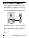
See “Quick Steps for Configuring an MST Region” on page 6-14 for a tutorial on how to configure MST
region parameters.
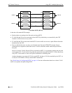
What is the Common Spanning Tree
The Common Spanning Tree (CST) is the overall network Spanning Tree topology resulting from STP,
RSTP, and/or MSTP calculations to provide a single data path through the network. CST provides connec-
tivity between MST regions and other MST regions and/or Single Spanning Tree (SST) switches. For
example, in the above diagram, CST calculations detected a network loop created by the connections
between Switch D, Switch E, and the MST Region. As a result, one of the paths was blocked.
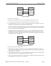
What is the Internal Spanning Tree (IST) Instance
The IST instance determines and maintains the CST topology between MST switches that belong to the
same MST region. In other words, the IST is simply a CST that only applies to MST Region switches
while at the same time representing the region as a single Spanning Tree bridge to the network CST.
As shown in the above diagram, the redundant path between Switch B and Switch C is blocked and the
path between Switch A and Switch C is blocked. These blocking decisions were based on IST computa-
tions within the MST region. IST sends and receives BPDU to/from the network CST. MSTI within the
region do not communicate with the network CST. As a result, the CST only sees the IST BPDU and
treats the MST region as a single Spanning Tree bridge.
What is the Common and Internal Spanning Tree Instance
The Common and Internal Spanning Tree (CIST) instance is the Spanning Tree calculated by the MST
region IST and the network CST. The CIST is represented by the single Spanning Tree flat mode instance
that is available on all switches. By default, all VLANs are associated to the CIST until they are mapped
to an MSTI.
When using STP (802.1D) or RSTP (802.1w), the CIST is also known as instance 1 or bridge 1. When
using MSTP (802.1s), the CIST is also known as instance 0 or MSTI 0.
Note that when MSTP (802.1s) is the active flat mode protocol, explicit Spanning Tree bridge commands
are required to configure parameter values. Implicit commands are for configuring parameters when the
STP or RSTP protocols are in use. See “Using Spanning Tree Configuration Commands” on page 6-10 for
more information.