Configuring VRRP VRRP Application Example
OmniSwitch 6600 Family Network Configuration Guide April 2006 page 19-17
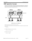
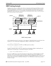
VRRP Tracking Example
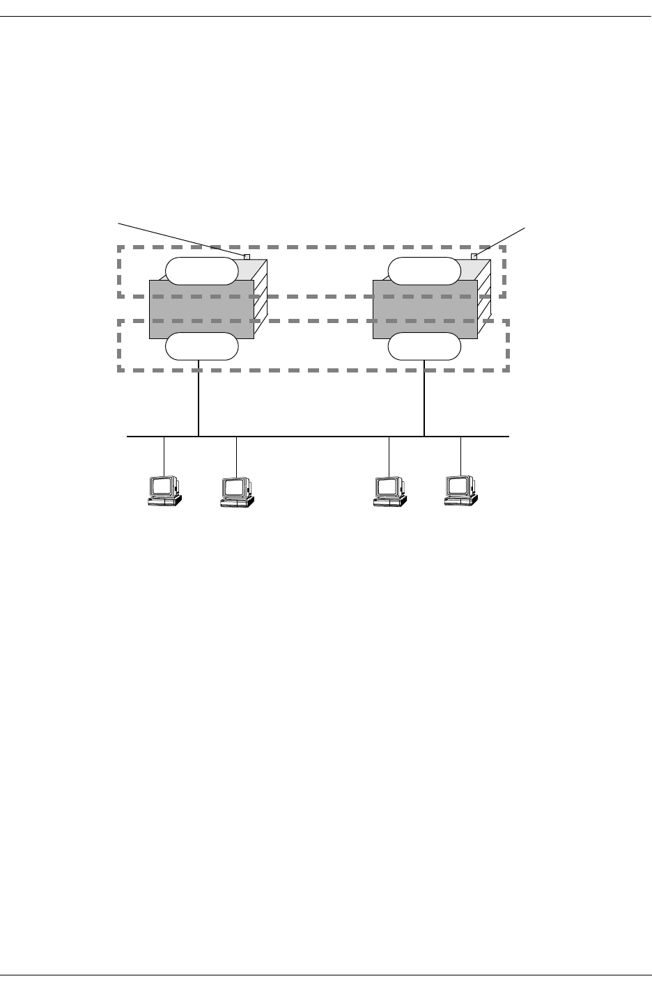
The figure below shows two VRRP routers with two virtual routers backing up one IP address on each
VRRP router respectively. Virtual router 1 serves as the default gateway on OmniSwitch A for clients 1
and 2 through IP address 10.10.2.250. For example, if the port that provides access to the Internet on
OmniSwitch A fails, virtual router 1 will continue to be the default router for clients 1 and 2 but clients 1
and 2 will not be able to access the Internet.
In this example, the master for virtual router 1 has a priority of 100 and the backup for virtual router 1 has
a priority of 75. The virtual router configuration for VRID 1 on VRRP router A is as follows:
-> vrrp 1 5 priority 100
The virtual router configuration for VRID 1 on VRRP router B is as follows:
-> vrrp 1 5 priority 75 preempt
To ensure workstation clients 1 and 2 have connectivity to the internet, configure a tracking policy on
VRRP router A to monitor port 3/1 and associate the policy with VRID 1.
-> vrrp track 1 enable priority 50 port 3/1
-> vrrp 1 5 track-association 1
If port 3/1 on VRRP router A goes down, the master for virtual router A is still functioning but worksta-
tion clients 1 and 2 will not be able to get to the Internet. With this tracking policy enabled, however,
master router 1’s priority will be temporarily decremented to 50, allowing backup router 1 to take over and
provide connectivity for those workstations. When port 3/1 on VRRP router A comes back up, master 1
will take over again.
VRRP Router
OmniSwitch A
VRRP Router
OmniSwitch B
Virtual Routers
VRID 1
10.10.2.250
VRID 2
10.10.2.245
VRRP Tracking Example
Master 1
10.10.2.21510.10.2.210
default gateway 10.10.2.250
default gateway 10.10.2.245
clients 3 and 4clients 1 and 2
Backup 2
Backup 1
Master 2
VLAN 5
port 3/1
port 3/1


