


105
CHAPTER 5 CPU ARCHITECTURE
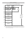
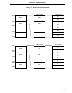
RETI and RETB
Instruction
PSW
PC15-PC8
PC15-PC8
PC7-PC0
Register Pair Lower
SP SP + 2
SP
Register Pair Upper
RET InstructionPOP rp Instruction
SP + 1
PC7-PC0
SP SP + 2
SP
SP + 1
SP + 2
SP
SP + 1
SP SP + 3
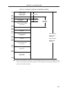
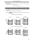
Interrupt and
BRK Instruction
PSW
PC15-PC8
PC15-PC8
PC7-PC0
Register Pair Lower
SP SP
_
2
SP
_
2
Register Pair Upper
CALL, CALLF, and
CALLT Instruction
PUSH rp Instruction
SP
_
1
SP
SP SP
_
2
SP
_
2
SP
_
1
SP
PC7-PC0
SP
_
3
SP
_
2
SP
_
1
SP
SP SP
_
3
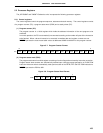
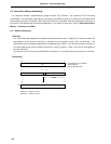
(3) Stack pointer (SP)
This is a 16-bit register to hold the start address of the memory stack area. Only the internal high-speed RAM
area (FB00H to FEFFH) can be set as the stack area.
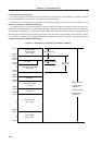
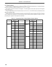
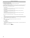
Figure 5-9. Stack Pointer Format
The SP is decremented ahead of write (save) to the stack memory and is incremented after read (reset) from
the stack memory.
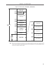
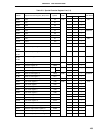
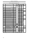
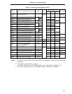
Each stack operation saves/resets data as shown in Figures 5-10 and 5-11.
Caution Since RESET input makes SP contents indeterminate, be sure to initialize the SP before
instruction execution.
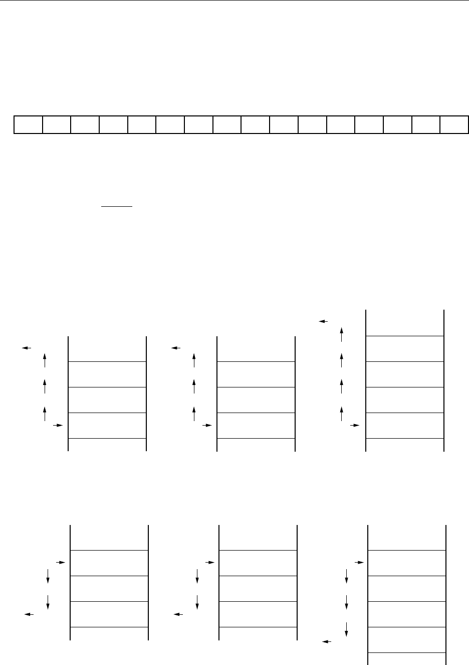
Figure 5-10. Data to Be Saved to Stack Memory
Figure 5-11. Data to Be Reset from Stack Memory
SP15SP SP14 SP13 SP12 SP11 SP10 SP9 SP8 SP7 SP6 SP5 SP4 SP3 SP2 SP1 SP0
15 0