


236
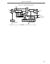
CHAPTER 9 8-BIT TIMER/EVENT COUNTERS
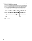
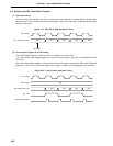
TI1, TI2, Input
CR10, CR20
TM1, TM2 Count Value
TO1, TO2
Interrupt Request Flag
00H
00H 00H 00H 00H
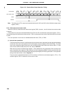
Count Pulse
TM1, TM2 Count Value
00H 01H 02H 03H 04H
Timer Start
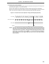
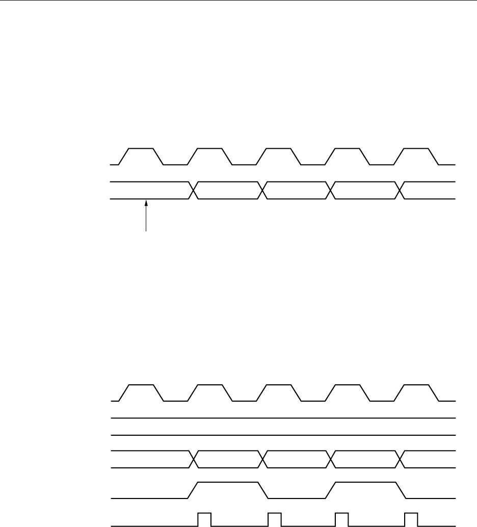
9.5 Cautions on 8-Bit Timer/Event Counters
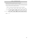
(1) Timer start errors
An error of one clock maximum may occur concerning the time required for a match signal to be generated
after timer start. This is because the 8-bit timer registers 1 and 2 (TM1 and TM2) are started asynchronously
with the count pulse.
Figure 9-14. 8-Bit Timer Registers Start Timing
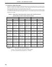
(2) 8-bit compare register 10 and 20 setting
The 8-bit compare registers 10 and 20 (CR10 and CR20) can be set to 00H.
Thus, when these 8-bit compare registers are used as event counters, one-pulse count operation can be
carried out.
When the 8-bit compare register is used as 16-bit timer/event counter, write data to CR10 and CR20 after
setting bit 0 (TCE1) of the 8-bit timer mode control register 1 (TMC1) to 0 and stopping timer operation.
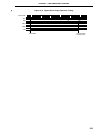
Figure 9-15. Event Counter Operation Timing