


19
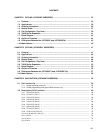
CHAPTER 11 WATCHDOG TIMER ...................................................................................................... 245
11.1 Watchdog Timer Functions ................................................................................................ 245
11.2 Watchdog Timer Configuration .......................................................................................... 247
11.3 Watchdog Timer Control Registers ................................................................................... 248
11.4 Watchdog Timer Operations............................................................................................... 251
11.4.1 Watchdog timer operation ....................................................................................................... 251
11.4.2 Interval timer operation ............................................................................................................ 252
CHAPTER 12 CLOCK OUTPUT CONTROL CIRCUIT ......................................................................... 253
12.1 Clock Output Control Circuit Functions ............................................................................ 253
12.2 Clock Output Control Circuit Configuration ..................................................................... 254
12.3 Clock Output Function Control Registers ......................................................................... 254
CHAPTER 13 BUZZER OUTPUT CONTROL CIRCUIT ....................................................................... 257
13.1 Buzzer Output Control Circuit Functions .......................................................................... 257
13.2 Buzzer Output Control Circuit Configuration ................................................................... 257
13.3 Buzzer Output Function Control Registers ....................................................................... 258
CHAPTER 14 A/D CONVERTER .......................................................................................................... 261
14.1 A/D Converter Functions .................................................................................................... 261
14.2 A/D Converter Configuration .............................................................................................. 262
14.3 A/D Converter Control Registers ....................................................................................... 265
14.4 A/D Converter Operations................................................................................................... 269
14.4.1 Basic operations of A/D converter ........................................................................................... 269
14.4.2 Input voltage and conversion results ....................................................................................... 271
14.4.3 A/D converter operating mode ................................................................................................ 272
14.5 A/D Converter Cautions ...................................................................................................... 274
CHAPTER 15 D/A CONVERTER .......................................................................................................... 279
15.1 D/A Converter Functions .................................................................................................... 279
15.2 D/A Converter Configuration .............................................................................................. 280
15.3 D/A Converter Control Registers ....................................................................................... 282
15.4 Operations of D/A Converter .............................................................................................. 283
15.5 Cautions Related to D/A Converter .................................................................................... 284
CHAPTER 16 SERIAL INTERFACE CHANNEL 0 (
µ
PD78058F SUBSERIES) ................................... 285
16.1 Serial Interface Channel 0 Functions................................................................................. 286
16.2 Serial Interface Channel 0 Configuration .......................................................................... 288
16.3 Serial Interface Channel 0 Control Registers.................................................................... 292
16.4 Serial Interface Channel 0 Operations ............................................................................... 299
16.4.1 Operation stop mode ............................................................................................................... 299
16.4.2 3-wire serial I/O mode operation ............................................................................................. 300