


225
CHAPTER 9 8-BIT TIMER/EVENT COUNTERS
9.4 8-Bit Timer/Event Counter Operation
9.4.1 8-bit timer/event counter mode
(1) Interval timer operations
Operates as an interval timer which generates interrupt requests repeatedly with the count values set
previously in the 8 bit conveyor registers 10 and 20 (CR10, CR20) as the interval.
When the count values of the 8-bit timer registers 1 and 2 (TM1 and TM2) match the values set to CR10 and
CR20, counting continues with the TM1 and TM2 values cleared to 0 and the interrupt request signals (INTTM1
and INTTM2) are generated.
Count clock of TM1 can be selected with bits 0 to 3 (TCL10 to TCL13) of the timer clock select register 1 (TCL1).
Count clock of TM2 can be selected with bits 4 to 7 (TCL14 to TCL17) of the timer clock select register 1 (TCL1).
For the operation when the value of the compare register has been changed during timer count operation,
refer to section 9.5 (3) Operation after compare register change during timer count operation.
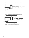
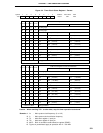
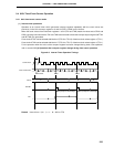
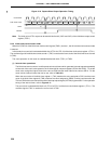
Figure 9-8. Interval Timer Operation Timings
Remark Interval time = (N + 1) × t : N = 00H to FFH
Count Clock
TM1 Count Value
INTTM1
CR10
TO1
Interval Time Interval Time Interval Time
Interrupt Request Acknowledge Interrupt Request Acknowledge
NNNN
Count Start Clear Clear
t
00 01 N 00 01 N 00 01 N