


269
CHAPTER 14 A/D CONVERTER
14.4 A/D Converter Operations
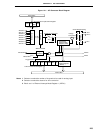
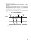
14.4.1 Basic operations of A/D converter
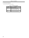
(1) Set the number of analog input channels with A/D converter input select register (ADIS).
(2) From among the analog input channels set with ADIS, select one channel for A/D conversion with A/D converter
mode register (ADM).
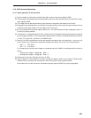
(3) The voltage input to the selected analog input channel is sampled by the sample & hold circuit.
(4) Sampling for the specified period of time sets the sample & hold circuit to the hold state so that the circuit
holds the input analog voltage until termination of A/D conversion.
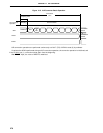
(5) Bit 7 of the sequential conversion register (SAR) is set. The serial resistance string’s voltage tap is set at (1/
2) AV
REF0 by the tap selector.
(6) The difference in voltages between the serial resistance string’s voltage tap and the analog input is compared
by the voltage comparator. If the analog input is greater than (1/2) AVREF0, the MSB of SAR remains set as
is. Also, if it is less than (1/2) AV
REF0, the MSB is reset.
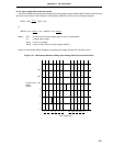
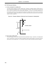
(7) Next, bit 6 of SAR is automatically set and the operation proceeds to the next comparison. In this case, the
series resistor string voltage tap is selected according to the preset value of bit 7 as described below.
• Bit 7 = 1 : (3/4) AV
REF0
• Bit 7 = 0 : (1/4) AVREF0
The voltage tap and analog input voltage are compared and bit 6 of SAR is manipulated with the result as
follows.
• Analog input voltage ≥ Voltage tap : Bit 6 = 1
• Analog input voltage < Voltage tap : Bit 6 = 0
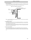
(8) Comparison of this sort continues up to bit 0 of SAR.
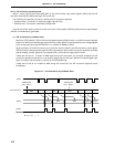
(9) Upon completion of the comparison of 8 bits, any effective digital resultant value remains in SAR and the
resultant value is transferred to and latched in the A/D conversion result register (ADCR).
At the same time, the A/D conversion termination interrupt request (INTAD) can also be generated.