


484
CHAPTER 21 INTERRUPT AND TEST FUNCTIONS
7
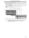
PMK6
Symbol
MK0L
6
PMK5
5
PMK4
4
PMK3
3
PMK2
2
PMK
1
PMK
0
TMMK4
Address
FFE4H FFH
After
Reset
R/W
R/W
× ×
MK
×
0
1
Interrupt Servicing Control
Interrupt servicing enabled
Interrupt servicing disabled
7
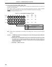
TMMK01
MK0H
6
TMMK00
5
TMMK3
4
STMK
3
SRMK
2
SERMK
1
CSIMK1
0
CSIMK0
7
WTMK
Note
MK1L
6
1
5
1
4
1
3
1
2
ADMK
1
TMMK2
0
TMMK1
FFE5H FFH R/W
FFE6H FFH R/W
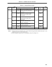
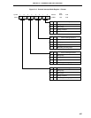
Note WTMK controls enable/disable of cancellation of the standby mode. It does not control the interrupt
function.
Cautions 1. If TMMK4 flag is read when a watchdog timer is used in watchdog timer mode 1, MK0 value
becomes undefined.
2. Because port 0 has an alternate function as the external interrupt request input, when
the output level is changed by specifying the output mode of the port function, an
interrupt request flag is set. Therefore, 1 should be set in the interrupt mask flag before
using the output mode.
3. Set always 1 in MK1L bits 3 to 6.
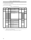
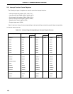
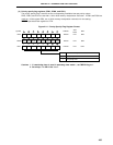
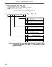
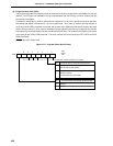
(2) Interrupt mask flag registers (MK0L, MK0H, MK1L)
The interrupt mask flag is used to enable/disable the corresponding maskable interrupt service and to set
standby clear enable/disable.
MK0L, MK0H, and MK1L are set with a 1-bit or 8-bit memory manipulation instruction. If MK0L and MK0H
are used as a 16-bit register MK0, use a 16-bit memory manipulation instruction for the setting.
RESET input sets these registers to FFH.
Figure 21-3. Interrupt Mask Flag Register Format