


88
CHAPTER 4 PIN FUNCTION (
µ
PD78058FY SUBSERIES)
4.2.9 P120 to P127 (Port 12)
These are 8-bit input/output ports. Besides serving as input/output ports, they function as a real-time output port.
The following operating modes can be specified bit-wise.
(1) Port mode
These ports function as 8-bit input/output ports. They can be specified bit-wise as input or output ports with
port mode register 12 (PM12). When they are used as input ports, on-chip pull-up resistors can be used by
defining the pull-up resistor option register H (PUOH).
(2) Control mode
These ports function as real-time output ports (RTP0 to RTP7) outputting data in synchronization with a trigger.
4.2.10 P130 and P131 (Port 13)
These are 2-bit input/output ports. Besides serving as input/output ports, they are used for D/A converter analog
output.
The following operating modes can be specified bit-wise.
(1) Port mode
These ports function as 2-bit input/output ports. They can be specified bit-wise as input or output ports with
port mode register 13 (PM13). When they are used as input ports, on-chip pull-up resistors can be used by
defining the pull-up resistor option register H (PUOH).
(2) Control mode
These ports allow D/A converter analog output (ANO0 and ANO1).
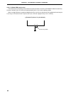
Caution When only either one of the D/A converter channels is used with AV
REF1< VDD, the other pins
that are not used as analog outputs must be set as follows:
• Set PM13× bit of the port mode register 13 (PM13) to 1 (input mode) and connect the pin
to V
SS.
• Set PM13× bit of the port mode register 13 (PM13) to 0 (output mode) and the output latch
to 0, to output low level from the pin.
4.2.11 AV
REF0
A/D converter reference voltage input pin.
When A/D converter is not used, connect this pin to VSS.
4.2.12 AV
REF1
D/A converter reference voltage input pin.
When D/A converter is not used, connect this pin to V
DD.