


409
CHAPTER 18 SERIAL INTERFACE CHANNEL 1
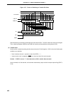
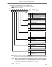
Data Transfer Interval Specification (f
XX
= 2.5 MHz Operation)
ADTI4 ADTI3 ADTI2 ADTI1
1
1
1
1
1
1
1
1
1
1
1
1
1
1
1
1
0
0
0
0
0
0
0
0
1
1
1
1
1
1
1
1
0
0
0
0
1
1
1
1
0
0
0
0
1
1
1
1
0
0
1
1
0
0
1
1
0
0
1
1
0
0
1
1
Minimum
Note
446.4
s + 0.5/f
SCK
472.0
s + 0.5/f
SCK
497.6
s + 0.5/f
SCK
523.2
s + 0.5/f
SCK
548.8
s + 0.5/f
SCK
574.4
s + 0.5/f
SCK
600.0
s + 0.5/f
SCK
625.6
s + 0.5/f
SCK
651.2
s + 0.5/f
SCK
676.8
s + 0.5/f
SCK
702.4
s + 0.5/f
SCK
728.0
s + 0.5/f
SCK
753.6
s + 0.5/f
SCK
779.2
s + 0.5/f
SCK
804.8
s + 0.5/f
SCK
830.4
s + 0.5/f
SCK
Maximum
Note
449.6
s + 1.5/f
SCK
475.2
s + 1.5/f
SCK
500.8
s + 1.5/f
SCK
526.4
s + 1.5/f
SCK
552.0
s + 1.5/f
SCK
577.6
s + 1.5/f
SCK
603.2
s + 1.5/f
SCK
628.8
s + 1.5/f
SCK
654.4
s + 1.5/f
SCK
680.0
s + 1.5/f
SCK
705.6
s + 1.5/f
SCK
731.2
s + 1.5/f
SCK
756.8
s + 1.5/f
SCK
782.4
s + 1.5/f
SCK
808.0
s + 1.5/f
SCK
833.6
s + 1.5/f
SCK
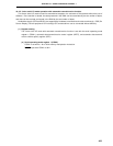
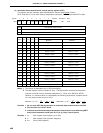
65432107
Symbol
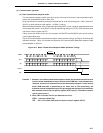
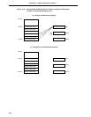
ADTI ADTI7 0 0 ADTI4 ADTI3 ADTI2 ADTI1 ADTI0
FF6BH 00H R/W
Address After Reset R/W
ADTI0
0
1
0
1
0
1
0
1
0
1
0
1
0
1
0
1
µ
µ
µ
µ
µ
µ
µ
µ
µ
µ
µ
µ
µ
µ
µ
µ
µ
µ
µ
µ
µ
µ
µ
µ
µ
µ
µ
µ
µ
µ
µ
µ
Note The data transfer interval includes an error. The data transfer minimum and maximum intervals
are found from the following expressions (n: Value set in ADTI0 to ADTI4). However, if a minimum
which is calculated by the following expressions is smaller than 2/f
SCK, the minimum interval time
is 2/fSCK.
Minimum = (n+1) × ++
Maximum = (n+1) × ++
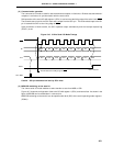
Cautions 1. Do not write ADTI during operation of automatic data transmit/receive function.
2. Bits 5 and 6 must be set to zero.
3. If the auto send and receive data transmission interval time is controlled using ADTI,
busy control becomes invalid (see 18.4.3 (4) (a) Busy control option).
Remarks 1. f
XX : Main system clock frequency (fX or fX/2)
2. fX : Main system clock oscillation frequency
3. fSCK : Serial clock frequency
2
6
fXX
2
6
fXX
28 0.5
f
XX fSCK
36 1.5
f
XX fSCK