


150
CHAPTER 6 PORT FUNCTIONS
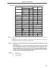
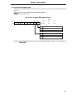
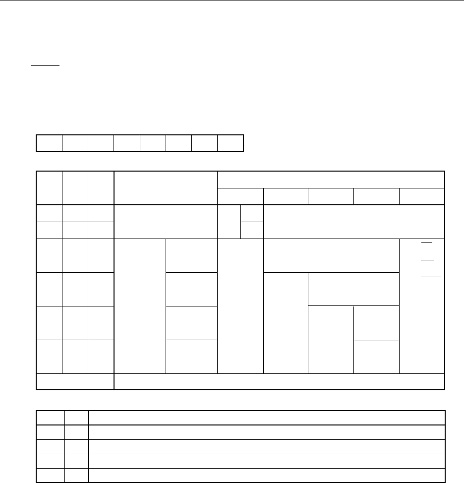
(3) Memory expansion mode register (MM)
This register is used to set input/output of port 4.
MM is set with a 1-bit or 8-bit memory manipulation instruction.
RESET input sets this register to 10H.
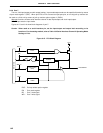
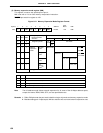
Figure 6-21. Memory Expansion Mode Register Format
Note The full address mode allows external expansion for all areas of the 64-Kbyte address space,
except the internal ROM, RAM, SFR, and use-prohibited areas.
Remarks 1. P60 to P63 pins enter the port mode in both the single-chip mode and memory expansion mode.
2. Besides setting port 4 input/output, MM also sets the wait count and external expansion area.
0 0 PW1 0MM FFF8H 10H R/W
765432Symbol Address
After
Reset R/W
1
PW0 MM2 MM1 MM0
0
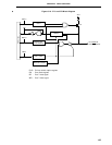
MM2 MM1 MM0
000
001
011
100
101
111
Other than above
Setting prohibited
Single-chip/Memory
Expansion Mode
Selection
Single-chip mode
256-byte
mode
4-Kbyte
mode
16-Kbyte
mode
Full
address
mode
Note
Memory
expansion
mode
AD0 to AD7
Input
Out-
put
Port
mode
P40 to P47
P40 to P47, P50 to P57, P64 to P67 Pin State
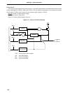
PW1
PW0
0
0
0
1
1
1
0
1
Wait Control
No wait
Wait (one wait state insertion)
Setting prohibited
Wait control by external wait pin
P56, P57 P64 to P67
Port mode
Port mode
Port mode
Port mode
A14, A15
A12, A13
P64=RD
P65=WR
P66=WAIT
P67=ASTB
P50 to P53 P54, P55
A8 to A11