


468
CHAPTER 19 SERIAL INTERFACE CHANNEL 2
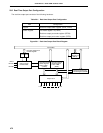
19.4.4 Restrictions on using UART mode
In the UART mode, a receive completion interrupt request (INTSR) is generated after a certain period of time
following the generation and clearing of the receive error interrupt request (INTSER). Thereby, the phenomenon
shown below may occur.
Details
If the bit 1 (ISRM) of the asynchronous serial interface mode register (ASIM) is set to 1, the setting is made
such that receive completion interrupt request (INTSR) will not be generated upon the generation of a receive
error. However, in the receive error interrupt request (INTSER) servicing, if the receive buffer register (RXB)
is read within a certain timing (“a” in Figure 19-14), internal error flag is cleared (to 0). Therefore, no receive
error is judged to have been generated, and INTSR, which is not supposed to be generated, will be generated.
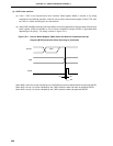
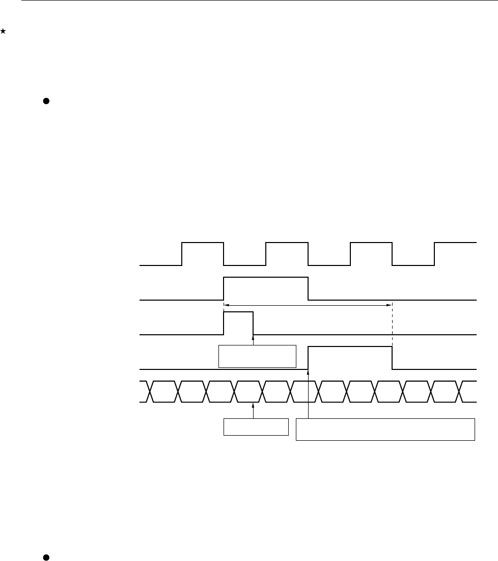
Figure 19-14 illustrates the operation above.
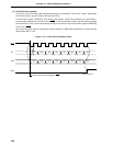
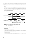
Figure 19-14. Receive Completion Interrupt Request Generation Timing (When ISRM = 1)
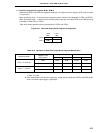
Remark ISRM : Bit 1 of asynchronous serial interface mode register (ASIM)
f
SCK : 5-bit counter source clock of baud rate generator
RXB : Receive buffer register
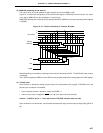
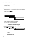
To avoid this phenomenon, implement the following countermeasures.
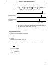
Countermeasures
• In the case of framing error or overrun error
Prohibit the reading of the receive buffer register (RXB) for a certain period (“T2” in Figure 19-15) after the
generation of a receive error interrupt request (INTSER).
• In the case of parity error
Prohibit the reading of the receive buffer register (RXB) for a certain period (“T1 + T2” in Figure 19-15) after
the generation of a receive error interrupt request (INTSER).
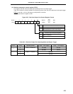
f
SCK
INTSR
Interrupt Servicing Routine
on CPU Side
Cleared Upon
Reading RXB
RXB Reading
INTSER (when Framing or
Overrun Error is Generated)
Judged no receive error has been generated,
and INTSR is generated.
Error Flag (Internal Flag)
a