


284
CHAPTER 15 D/A CONVERTER
15.5 Cautions Related to D/A Converter
(1) Output impedance of D/A converter
Because the output impedance of the D/A converter is high, use of current flowing from the ANOn pins
(n = 0,1) is prohibited. If the input impedance of the load for the converter is low, insert a buffer amplifier
between the load and the ANOn pins. In addition, wiring from the ANOn pins to the buffer amplifier or the
load should be as short as possible (because of high output impedance). If the wiring may be long, design
the ground pattern so as to be close to those lines or use some other expedient to achieve shorter wiring.
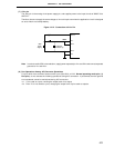
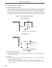
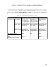
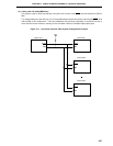
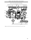
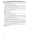
Figure 15-3. Use Example of Buffer Amplifier
(a) Inverting amplifier
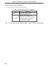
(b) Voltage-follower
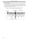
(2) Output voltage of D/A converter
Because the output voltage of the converter changes in steps, use the D/A converter output signals in general
by connecting a low-pass filter.
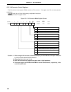
(3) AV
REF1 pin
When only either one of the D/A converter channels is used with AV
REF1 < VDD, the pin that is not used as
an analog output must be set as follows.
• Set PM13 × bit of the port mode register 13 (PM13) to 1 (input mode) and connect the pin to VSS.
• Set PM13 × bit of the port mode register 13 (PM13) to 0 (output mode) and the output latch to 0, to output
low level from the pin.
µ
PD78058F, 78058FY
ANOn
R
1
C
R
2
• The input impedance of the buffer amplifier is R1.
PD78058F, 78058FY
ANOn
R
R
1
C
• The input impedance of the buffer amplifier is R
1
.
• If R
1
is not connected, the output becomes
undefined when RESET is low.
µ