


181
CHAPTER 8 16-BIT TIMER/EVENT COUNTER
0000
TMC03 TMC02 TMC01
OVF0
76543210Symbol
TMC0
FF48H 00H R/W
Address After Reset R/W
OVF0
16-Bit Timer Register Overflow Detection
0 Overflow not detected
1 Overflow detected
TMC03 TMC02 TMC01
Operating Mode
Clear Mode Selection
TO0 Output Timing Selection Interrupt Generation
000
Operation stop
(TM0 cleared to 0)
No change Not Generated
001
PWM mode
(free running)
PWM pulse output
010
011
100
101
110
111
Free running mode
Match between TM0 and
CR00 or match between
TM0 and CR01
Match between TM0 and
CR00, match between
TM0 and CR01 or TI00
valid edge
Match between TM0 and
CR00 or match between
TM0 and CR01
Match between TM0 and
CR00, match between
TM0 and CR01 or TI00
valid edge
Match between TM0 and
CR00 or match between
TM0 and CR01
Match between TM0 and
CR00, match between
TM0 and CR01 or TI00
valid edge
Clear & start on TI00
valid edge
Clear & start on match
between TM0 and CR00
Generated on match
between TM0 and CR00,
and match between TM0
and CR01
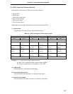
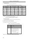
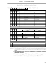
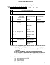
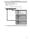
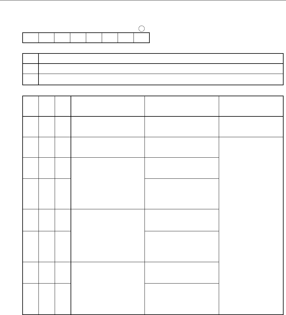
Figure 8-4. 16-Bit Timer Mode Control Register Format
Cautions 1. Switch the clear mode and the T00 output timing after stopping the timer operation
(by setting TMC01 to TMC03 to 0, 0, 0).
2. The valid edge of pin TI00/INTP0 is set with the external mode register 0 (INTM0). Also,
the frequency of the sampling clock is selected with the sampling clock selection
register (SCS).
3. When using the PWM mode, set the PWM mode and then set data to CR00.
4. If clear & start mode on match between TM0 and CR00 is selected, when the set value
of CR00 is FFFFH and the TM0 value changes from FFFFH to 0000H, OVF0 flag is set
to 1.
Remarks TO0 : 16-bit timer/event counter output pin
TI00 : 16-bit timer/event counter input pin
TM0 : 16-bit timer register
CR00 : Compare register 00
CR01 : Compare register 01