


483
CHAPTER 21 INTERRUPT AND TEST FUNCTIONS
7
PIF6
Symbol
IF0L
6
PIF5
5
PIF4
4
PIF3
3
PIF2
2
PIF1
1
PIF0
0
TMIF4
Address
FFE0H 00H
After
Reset
R/W
R/W
× × IF×
0
1
Interrupt Request Flag
No interrupt request signal
Interrupt request signal is generated;
Interrupt request state
7
TMIF01
IF0H
6
TMIF00
5
TMIF3
4
STIF
3
SRIF
2
SERIF
1
CSIIF1
0
CSIIF0
7
WTIF
Note
IF1L
6
0
5
0
4
0
3
0
2
ADIF
1
TMIF2
0
TMIF1
FFE1H 00H R/W
FFE2H 00H R/W
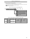
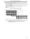
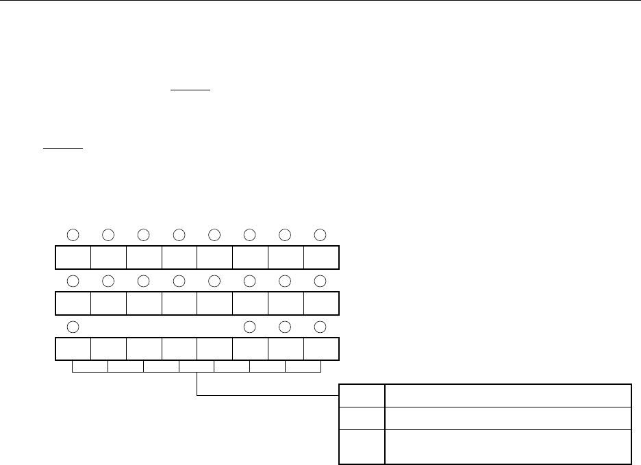
Note WTIF is test input flag. Vectored interrupt request is not generated.
Cautions 1. TMIF4 flag is R/W enabled only when a watchdog timer is used as an interval timer. If
a watchdog timer is used in watchdog timer mode 1, set TMIF4 flag to 0.
2. Set always 0 in IF1L bits 3 to 6.
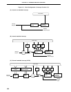
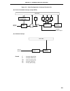
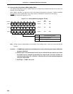
(1) Interrupt request flag registers (IF0L, IF0H, IF1L)
The interrupt request flag is set to 1 when the corresponding interrupt request is generated or an instruction
is executed. It is cleared to 0 when an instruction is executed upon acknowledgment of an interrupt request
or upon application of RESET input.
IF0L, IF0H, and IF1L are set with a 1-bit or 8-bit memory manipulation instruction. If IF0L and IF0H are used
as a 16-bit register IF0 use a 16-bit memory manipulation instruction for the setting.
RESET input sets these registers to 00H.
Figure 21-2. Interrupt Request Flag Register Format