


283
CHAPTER 15 D/A CONVERTER
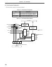
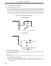
15.4 Operations of D/A Converter
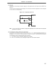
(1) Select the operation mode for channel 0 using bit 4 (DAM4) of the D/A converter mode register (DAM), and
select the operation mode for channel 1 using bit 5 (DAM5).
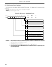
(2) Set data corresponding to the analog voltage values output respectively to pins ANO0/P130 and ANO1/P131
in D/A conversion setting registers 0 and 1 (DACS0 and DACS1).
(3) It is possible to start A/D conversion operation for channels 0 and 1 by setting bits 0 and 1 (DACE0, DACE1)
of DAM.
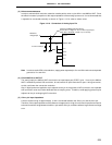
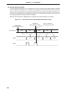
(4) After D/A conversion, when in the normal mode, analog voltages are output immediately to pins ANO0/P130
and ANO1/P131. When in the real time output mode, analog voltages are output in sync with the output trigger.
(5) In the normal mode, the analog voltage signals to be output are held until new data are set in DACS0 and
DACS1. In the realtime output mode, new data are set in DACS0 and DACS1 and then they are held until
the next trigger is generated.
Caution Set DACE0 and DACE1 after setting data in DACS0 and DACS1.