


233
CHAPTER 9 8-BIT TIMER/EVENT COUNTERS
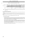
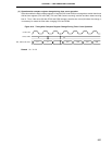
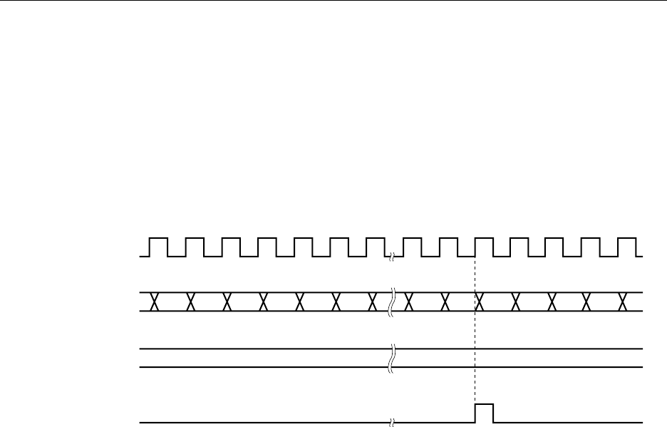
TI1 Pin Input
TM1, TM2 Count Value
CR10, CR20
INTTM2
0000 0001 0002 0003 0004 0005 N-1 N 0000 0001 0002 0003
N
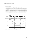
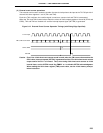
(2) External event counter operations
The external event counter counts the number of external clock pulses to be input to the TI1/P33 pin with 2-
channel 8-bit timer registers 1 and 2 (TM1 and TM2).
Each time TM1 overflows, the overflow signal is used as a counter clock and TM2 is incremented.
When the TM1 and TM2 counted values match the values of 8-bit compare registers 10 and 20 (CR10 and
CR20), TM1 and TM2 are cleared to 0 and the interrupt request signal (INTTM2) is generated.
Figure 9-12. External Event Counter Operation Timings (with Rising Edge Specified)
Caution Even if the 16-bit timer/event counter mode is used, when the TM1 count value matches the
CR10 value, interrupt request (INTTM1) is generated and the F/F of 8-bit timer/event counter
output control circuit 1 is inverted. Thus, when using 8-bit timer/event counter as 16-bit
interval timer, set the INTTM1 mask flag TMMK1 to 1 to disable INTTM1 acknowledgment.
When reading the 16-bit timer register (TMS) count value, use the 16-bit memory manipu-
lation instruction.