


369
CHAPTER 17 SERIAL INTERFACE CHANNEL 0 (
µ
PD78058FY SUBSERIES)
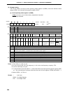
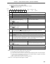
(b) Serial bus interface control register (SBIC)
SBIC is set by a 1-bit or 8-bit memory manipulation instruction.
RESET input sets SBIC to 00H.
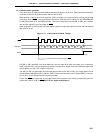
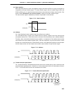
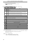
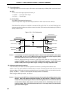
R/W RELT Use for stop condition output. When RELT = 1, SO0 latch is set to 1. After SO0 latch setting, automati-
cally cleared to 0. Also cleared to 0 when CSIE0 = 0.
R/W CMDT Use for start condition output. When CMDT = 1, SO0 latch is cleared to 0. After clearing SO0 latch,
automatically cleared to 0. Also cleared to 0 when CSIE0 = 0.
R RELD Stop Condition Detection
Clear Conditions (RELD = 0) Setting Condition (RELD = 1)
• When transfer start instruction is executed • When stop condition is detected
• If SIO0 and SVA values do not match in address reception
• When CSIE0 = 0
• When RESET input is applied
R CMDD Start Condition Detection
Clear Conditions (CMDD = 0) Setting Condition (CMDD = 1)
• When transfer start instruction is executed • When start condition is detected
• When stop condition is detected
• When CSIE0 = 0
• When RESET input is applied
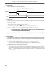
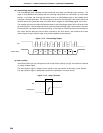
R/W ACKT SDA0 (SDA1) is set to low after the Set instruction execution (ACKT = 1) before the next SCL falling edge.
Used for generating an ACK signal by software if the 8-clock wait mode is selected. Cleared to 0 if
CSIE = 0 when a transfer by the serial interface is started.
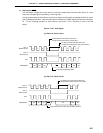
R/W ACKE Acknowledge Signal Automatic Output Control
Note 2
0 Disabled (with ACKT enabled). Used when receiving data in the 8-clock wait mode or when transmitting
data.
Note 3
1 Enabled.
After completion of transfer, acknowledge signal is output in synchronization with the 9th falling edge of
SCL clock (automatically output when ACKE = 1). However, not automatically cleared to 0 after acknowl-
edge signal output. Used for reception when the 9-clock wait mode is selected.
R ACKD Acknowledge Detection
Clear Conditions (ACKD = 0) Setting Condition (ACKD = 1)
• When transfer start instruction is executed • When acknowledge signal is detected at the rising
• When CSIE0 = 0 edge of SCL clock after completion of transfer
• When RESET input is applied
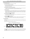
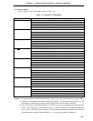
R/W BSYE
Control of N-ch Open-Drain Output for Transmission in I
2
C Bus Mode
Note 5
Note 4
0 Output enabled (transmission)
1 Output disabled (reception)
Notes 1. Bits 2, 3, and 6 (RELD, CMDD, ACKD) are read-only bits.
2. This setting must be performed prior to transfer start.
3. In the 8-clock wait mode, use ACKT for output of the acknowledge signal after normal data reception.
4. The busy mode can be released by the start of a serial interface transfer or reception of an address
signal. However, the BSYE flag is not cleared.
5. When using the wake-up function, be sure to set BSYE to 1.
CSIE0: Bit 7 of Serial Operation Mode Register 0 (CSIM0)
65432107
Symbol
SBIC BSYE ACKD ACKE
FF61H 00H R/W
Note 1
Address After Reset R/W
ACKT
CMDD
RELD CMDT RELT