


312
CHAPTER 16 SERIAL INTERFACE CHANNEL 0 (
µ
PD78058F SUBSERIES)
READYACK
SCK0
SB0 (SB1)
BUSY
89
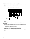
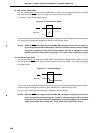
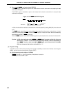
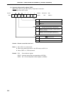
(f) Busy signal (BUSY) and ready signal (READY)
The BUSY signal is intended to report to the master device that the slave device is preparing for data
transmission/reception.
The READY signal is intended to report to the master device that the slave device is ready for data
transmission/reception.
Figure 16-19. BUSY and READY Signals
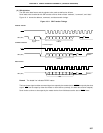
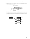
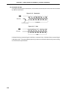
In SBI, the slave device notifies the master device of the busy state by setting SB0 (SB1) line to the low
level.
The BUSY signal output follows the acknowledge signal output from the master or slave device. It is set/
reset at the falling edge of SCK0. When the BUSY signal is reset, the master device automatically
terminates the output of SCK0 serial clock.
When the BUSY signal is reset and the READY signal is set, the master device can start the next transfer.
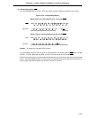
Caution In SBI, after specifying reset of BUSY, the BUSY signal is output until the fall of the next
serial clock. If WUP = 1 is set during this interval by mistake, it will be impossible to
reset BUSY. Therefore, after resetting the BUSY signal, confirm that the level of the SB0
(SB1) pin has gone high before setting WUP to “1”.
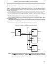
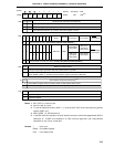
(3) Register setting
The SBI mode is set with serial operating mode register 0 (CSIM0), the serial bus interface control register
(SBIC), and the interrupt timing specify register (SINT).
(a) Serial operating mode register 0 (CSIM0)
CSIM0 is set with a 1-bit or 8-bit memory manipulation instruction.
RESET input sets CSIM0 to 00H.