


373
CHAPTER 17 SERIAL INTERFACE CHANNEL 0 (
µ
PD78058FY SUBSERIES)
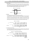
(7) Error detection
In the I
2
C bus mode, transmission error detection can be performed by the following methods because the
serial bus SDA0 (SDA1) status during transmission is also taken into the serial I/O shift register 0 (SIO0)
register of the transmitting device.
(a) Comparison of SIO0 data before and after transmission
In this case, a transmission error is judged to have occurred if the two data values are different.
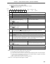
(b) Using the slave address register (SVA)
Transmit data is set in SIO0 and SVA before transmission is performed. After transmission, the COI bit
(match signal from the address comparator) of serial operating mode register 0 (CSIM0) is tested: "1"
indicates normal transmission, and "0" indicates a transmission error.
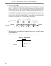
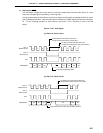
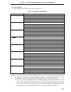
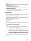
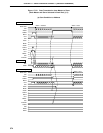
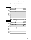
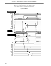
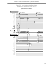
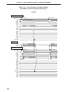
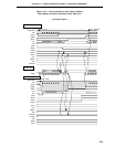
(8) Communication operation
In the I
2
C bus mode, the master selects the slave device to be communicated with from among multiple
devices by outputting address data onto the serial bus.
After the slave address data, the master sends the R/W bit which indicates the data transfer direction, and
starts serial communication with the selected slave device.
Data communication timing charts are shown in Figures 17-22 and 17-23.
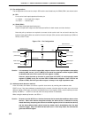
In the transmitting device, the serial I/O shift register 0 (SIO0) shifts transmission data to the SO latch in
synchronization with the falling edge of the serial clock (SCL), the SO0 latch outputs the data on an MSB-
first basis from the SDA0 or SDA1 pin to the receiving device.
In the receiving device, the data input from the SDA0 or SDA1 pin is taken into the SIO0 in synchroniza-
tion with the rising edge of SCL.
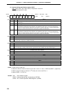
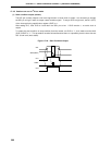
(9) Start of transfer
A serial transfer is started by setting transfer data in serial I/O shift register 0 (SIO0) if the following two
conditions have been satisfied:
• The serial interface channel 0 operation control bit (CSIE0) = 1.
• After an 8-bit serial transfer, the internal serial clock is stopped or SCL is low.
Cautions 1. Be sure to set CSIE0 to 1 before writing data in SIO0. Setting CSIE0 to 1 after writing
data in SIO0 does not initiate transfer operation.
2. It is necessary for the N-ch open drain output to be set in the high impedance state when
receiving data, so set 1 in bit 7 (BSYE) of the serial bus interface control register (SBIC)
in advance and write FFH in serial I/O shift register 0 (SIO0).
However, when the wake up function is used (when bit 5 (WUP) of serial operation mode
register 0 (CSIM0) is set), do not write FFH in SIO0 before reception. Even if FFH is not
written in SIO0, the N-ch open drain output is always in the high impedance state.
3. If data is written to SIO0 while the slave is in the wait state, that data is held. The transfer
is started when SCL is output after the wait state is cleared.
When an 8-bit data transfer ends, serial transfer is stopped automatically and the interrupt request flag
(CSIIF0) is set.