


174
CHAPTER 8 16-BIT TIMER/EVENT COUNTER
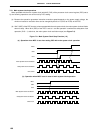
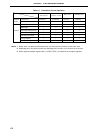
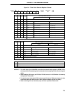
(5) Square-wave output
TM0 can output a square wave with any selected frequency.
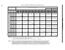
Table 8-3. 16-Bit Timer/Event Counter Square-Wave Output Ranges
Minimum Pulse Width Maximum Pulse Width Resolution
MCS = 1 MCS = 0 MCS = 1 MCS = 0 MCS = 1 MCS = 0
2 × TI00 input cycle 2
16
× TI00 input cycle TI00 input edge cycle
2 × 1/fX 2
16
× 1/fX 1/fX
(400 ns) (13.1 ms) (200 ns)
2 × 1/fX 2
2
× 1/fX 2
16
× 1/fX 2
17
× 1/fX 1/fX 2 × 1/fX
(400 ns) (800 ns) (13.1 ms) (26.2 ms) (200 ns) (400 ns)
2
2
× 1/fX 2
3
× 1/fX 2
17
× 1/fX 2
18
× 1/fX 2 × 1/fX 2
2
× 1/fX
(800 ns) (1.6
µ
s) (26.2 ms) (52.4 ms) (400 ns) (800 ns)
2
3
× 1/fX 2
4
× 1/fX 2
18
× 1/fX 2
19
× 1/fX 2
2
× 1/fX 2
3
× 1/fX
(1.6
µ
s) (3.2
µ
s) (52.4 ms) (104.9 ms) (800 ns) (1.6
µ
s)
2 × watch timer output cycle 2
16
× watch timer output cycle Watch timer output edge cycle
Remarks 1. fX: Main system clock oscillation frequency
2. MCS: Bit 0 of oscillation mode selection register (OSMS)
3. Values in parentheses when operated at f
X = 5.0 MHz
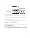
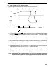
(6) One-shot pulse output
TM0 is able to output one-shot pulse which can set any width of output pulse.
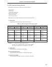
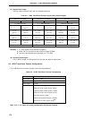
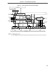
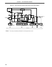
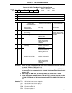
8.3 16-Bit Timer/Event Counter Configuration
The 16-bit timer/event counter consists of the following hardware.
Table 8-4. 16-Bit Timer/Event Counter Configuration
Item Configuration
Timer register 16 bits × 1 (TM0)
Register Capture/compare register: 16 bits × 2 (CR00, CR01)
Timer output 1 (TO0)
Control register Timer clock select register 0 (TCL0)
16-bit timer mode control register (TMC0)
Capture/compare control register 0 (CRC0)
16-bit timer output control register (TOC0)
Port mode register 3 (PM3)
External interrupt mode register 0 (INTM0)
Sampling clock select register (SCS)
Note
Note Refer to the Figure 21-1 Basic Configuration of Interrupt Function.
———