


458
CHAPTER 19 SERIAL INTERFACE CHANNEL 2
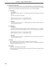
(d) Reception
When bit 6 (RXE) of the asynchronous serial interface mode register (ASIM) is set (1), a receive operation
is enabled and sampling of the RxD pin input is performed.
RxD pin input sampling is performed using the serial clock specified by ASIM.
When the RxD pin input becomes low, the baud rate generator’s 5 bit counter (see Figure 19-2) starts
counting, and at the time when the half time determined by specified baud rate has passed, the data
sampling start timing signal is output. If the RxD pin input sampled again as a result of this start timing
signal is low, it is identified as a start bit, the 5-bit counter is initialized and starts counting, and data
sampling is performed. When character data, a parity bit and one stop bit are detected after the start
bit, reception of one frame of data ends.
When one frame of data has been received, the receive data in the shift register is transferred to the receive
buffer register (RXB), and a reception completion interrupt request (INTSR) is generated.
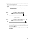
Even if an error occurs, the receive data for which the error occurred is transferred to RXB. When an
error occurs, if bit 1 (ISRM) of ASIM is cleared (0), INTSR is generated. If ISRM is set (1), INTSR is not
generated.
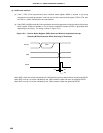
If the RXE bit is reset (0) during the receive operation, the receive operation is stopped immediately. In
this case, the contents of RXB and ASIS are not changed, and INTSR and INTSER are not generated.
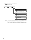
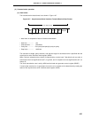
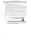
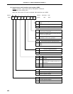
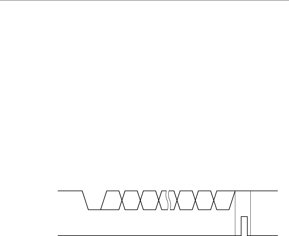
Figure 19-9. Asynchronous Serial Interface Reception Completion Interrupt Request Generation Timing
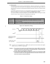
Caution The receive buffer register (RXB) must be read even if a receive error is generated. If
RXB is not read, an overrun error will be generated when the next data is received, and
the receive error state will continue indefinitely.
D1 D2 D6 D7 ParityD0RxD (Input)
INTSR
STOP
START