


219
CHAPTER 9 8-BIT TIMER/EVENT COUNTERS
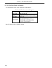
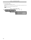
(1) Compare registers 10 and 20 (CR10, CR20)
These are 8-bit registers to compare the value set to CR10 to the 8-bit timer register 1 (TM1) count value,
and the value set to CR20 to the 8-bit timer register 2 (TM2) count value, and, if they match, generate an
interrupt request (INTTM1 and INTTM2, respectively).
CR10 and CR20 are set with an 8-bit memory manipulation instruction. They cannot be set with a 16-bit
memory manipulation instruction. When the compare register is used as 8-bit timer/event counter, the 00H
to FFH values can be set. When the compare register is used as 16-bit timer/event counter, the 0000H to
FFFFH values can be set.
RESET input makes CR10 and CR20 undefined.
Cautions 1. When using the compare register as a 16-bit timer/event counter, be sure to stop the timer
operation before setting data.
2. If the values after CR10 and CR20 are changed smaller than those of the 8-bit timer registers
(TM1 and TM2), TM1 and TM2 continue counting, overflow, and then restart counting from
0. Thus, if the values after CR10 and CR20 change are smaller than the values before the
change, it is necessary to restart the timer after changing CR10 and CR20.
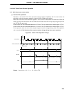
(2) 8-bit timer registers 1, 2 (TM1, TM2)
These are 8-bit registers to count count pulses.
When TM1 and TM2 are used in the 8-bit timer × 2-channel mode, they are read with an 8-bit memory manip-
ulation instruction. When TM1 and TM2 are used as 16-bit timer × 1-channel mode, 16-bit timer register (TMS)
is read with a 16-bit memory manipulation instruction.
RESET input sets TM1 and TM2 to 00H.