


147
CHAPTER 6 PORT FUNCTIONS
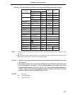
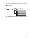
Table 6-5. Port Mode Register and Output Latch Settings When Using Alternate Functions
P00
INTP0 Input 1 (Fixed) None
TI00 Input 1 (Fixed) None
P01
INTP1 Input 1 ×
TI01 Input 1 ×
P02 to P06
INTP2 to INTP6
Input 1 ×
P07
Note 1
XT1 Input 1 (Fixed) None
P10 to P17
Note 1
ANI0 to ANI7 Input 1 ×
P30 to P32 TO0 to TO2 Output 0 0
P33, P34 TI1, TI2 Input 1 ×
P35 PCL Output 0 0
P36 BUZ Output 0 0
P40 to P47 AD0 to AD7
Input/Output
×
Note 2
P50 to P57 A8 to A15 Output ×
Note 2
P64 RD Output ×
Note 2
P65 WR Output ×
Note 2
P66 WAIT Input ×
Note 2
P67 ASTB Output ×
Note 2
P120 to P127
RTP0 to RTP7
Output 0 desired value
P130, P131
Note 1
ANO0, ANO1 Output 1 ×
Alternate Functions
Name
P××
PM××
Input/Output
Pin Name
Notes 1. If these ports are read out when these pins are used in the alternate function mode, undefined values
are read.
2. When the P40 to P47 pins P50 to P57 pins, and P64 to P67 pins are used for alternate functions, set
the function by the memory expansion mode register (MM).
Cautions 1. When not using external wait in the external memory extension mode, the P66 pin can be used
as an I/O port.
2. When port 2 and port 7 are used for serial interface pin, the I/O latch or output latch must
be set according to its function. For the setting methods, see Figure 16-4 “Serial
Operation Mode Register 0 Format,” Figure 17-4 “Serial Operating Mode Register 0
Format,” Figure 18-3 “Serial Operating Mode Register 1 Format”, and Table 19-2 “Serial
Interface Channel 2 Operating Mode Settings of List”.
Remarks × : don’t care
PM×× : port mode register
P×× : port output latch