


99
CHAPTER 5 CPU ARCHITECTURE
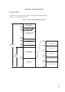
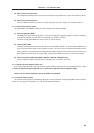
(2) CALLT instruction table area
The 64-byte area 0040H to 007FH can store the subroutine entry address of a 1-byte call instruction (CALLT).
(3) CALLF instruction entry area
The area 0800H to 0FFFH can perform a direct subroutine call with a 2-byte call instruction (CALLF).
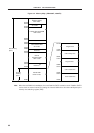
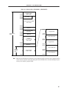
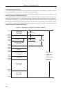
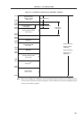
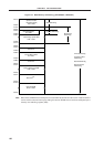
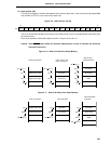
5.1.2 Internal data memory space
The
µ
PD78058F and 78058FY Subseries units incorporate the following RAMs.
(1) Internal high-speed RAM
This RAM has a 1024 x 8 bit configuration. In this area, four banks of general registers, each bank consisting
of eight 8-bit registers, are allocated in the 32-byte area FEE0H to FEFFH.
The internal high-speed RAM can also be used as a stack memory.
(2) Internal buffer RAM
Internal buffer RAM is allocated to the 32-byte area from FAC0H to FADFH. The internal buffer RAM is used
to store transmit/receive data of serial interface channel 1 (in 3-wire serial I/O mode with automatic transfer/
receive function). If the 3-wire serial I/O mode with automatic transfer/receive function is not used, the internal
buffer RAM can also be used as normal RAM. Internal buffer RAM can also be used as normal RAM.
(3) Internal expansion RAM (
µ
PD78058F, 78058FY, 78P058F, 78P058FY only)
Internal expansion RAM is allocated to the 1024-byte area from F400H to F7FFH.
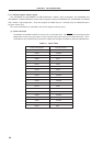
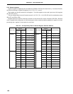
5.1.3 Special Function Register (SFR) area
An on-chip peripheral hardware special-function register (SFR) is allocated in the area FF00H to FFFFH. (Refer
to Table 5-3. Special-Function Register List in Section 5.2.3 Special Function Register (SFR)).
Caution Do not access addresses where the SFR is not assigned.
5.1.4 External memory space
The external memory space is accessible by setting the memory expansion mode register (MM). External memory
space can store program, table data, etc. and allocate peripheral devices.