


62
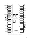
CHAPTER 3 PIN FUNCTION (
µ
PD78058F SUBSERIES)
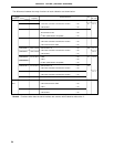
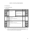
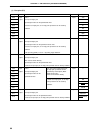
(2) Non-port pins (1/2)
Pin Name
Input/Output
Function After Reset
Alternate Function
INTP0 Input External interrupt request inputs with specifiable valid edges (rising Input P00/TI00
INTP1 edge, falling edge, both rising and falling edges). P01/TI01
INTP2 P02
INTP3 P03
INTP4 P04
INTP5 P05
INTP6 P06
SI0 Input Serial interface serial data input Input P25/SB0
SI1 P20
SI2 P70/RxD
SO0 Output Serial interface serial data output Input P26/SB1
SO1 P21
SO2 P71/TxD
SB0 Input/ Serial interface serial data input/output Input P25/SI0
SB1 output P26/SO0
SCK0 Input/ Serial interface serial clock input/output Input P27
SCK1 output P22
SCK2 P72/ASCK
STB Output Serial interface automatic transmit/receive strobe output Input P23
BUSY Input Serial interface automatic transmit/receive busy input Input P24
RxD Input Asynchronous serial interface serial data input Input P70/SI2
TxD Output Asynchronous serial interface serial data output Input P71/SO2
ASCK Input Asynchronous serial interface serial clock input Input P72/SCK2
TI00 Input External count clock input to 16-bit timer (TM0) Input P00/INTP0
TI01 Capture trigger signal input to capture register (CR00) P01/INTP1
TI1 External count clock input to 8-bit timer (TM1) P33
TI2 External count clock input to 8-bit timer (TM2) P34
TO0 Output 16-bit timer (TM0) output (also used for 14-bit PWM output) Input P30
TO1 8-bit timer (TM1) output P31
TO2 8-bit timer (TM2) output P32
PCL Output Clock output (for main system clock and subsystem clock trimming) Input P35
BUZ Output Buzzer output Input P36
RTP0 to RTP7
Output Real-time output port outputting data in synchronization with trigger Input P120 to P127