


230
CHAPTER 9 8-BIT TIMER/EVENT COUNTERS
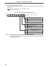
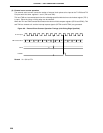
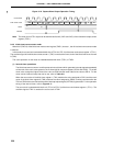
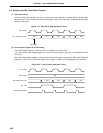
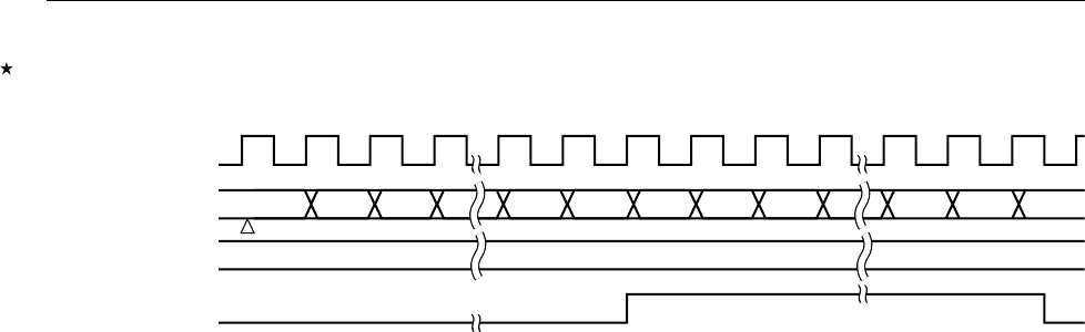
Figure 9-10. Square-Wave Output Operation Timing
Note The initial value of TO1 output can be set with bits 2 and 3 (LVR1 and LVS1) of the 8-bit timer output control
register (TOC1).
9.4.2 16-bit timer/event counter mode
When bit 2 (TMC12) of the 8-bit timer mode control register (TMC1) is set to 1, the 16-bit timer/event counter mode
is entered.
In this mode, the count clock is selected with bits 0 to 3 (TCL10 to TCL13) of the timer clock select register 1 (TCL1).
The overflow signal of the 8-bit timer/event counter 1 (TM1) is used as the count clock of the 8-bit timer/event counter
2 (TM2).
The count operation in this mode is enabled/disabled with bit 0 (TCE1) of TMC1.
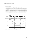
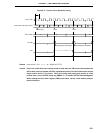
(1) Interval timer operations
The 8-bit timer/event counters 1 and 2 operate as interval timers which generate interrupt requests repeatedly
at intervals of the count value preset in the 2-channel 8-bit compare registers (CR10 and CR20). To set the
count value, assign the higher 8 bits of the value to CR20 and the lower 8 bits of the value to CR10. For the
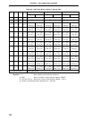
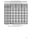
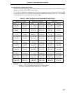
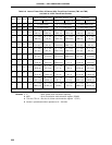
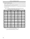
count values (interval times) that can be set, refer to Table 9-9.
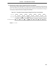
When the count value of the 8-bit timer register 1 (TM1) matches the value assigned to CR10 and the count
value of the 8-bit timer register 2 (TM2) matches the value assigned to CR20, counting continues after the
TM1 and TM2 values are cleared to 0 and the interrupt request signal (INTTM2) is generated. For the operation
timing of the interval timer, refer to Figure 9-11.
The count clock is selected with bits 0 to 3 (TCL10 to TCL13) of the timer clock select register 1 (TCL1). The
overflow signal of TM1 is used as the count clock of TM2.
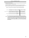
Count Clock
TM1 Count Value
00 01 02 N – 1 N 00 01 02 N – 1 N 00
CR10
TO1
Note
N
Count Start