


187
CHAPTER 8 16-BIT TIMER/EVENT COUNTER
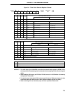
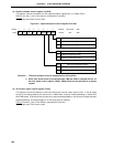
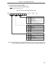
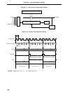
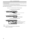
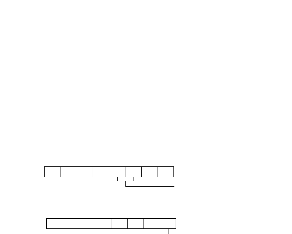
0 0 0 0 0 0/1 0/1 0
CRC02 CRC01 CRC00
CRC0
CR00 set as compare register
0000110/10
TMC03 TMC02 TMC01 OVF0
TMC0
Clear & start on match TM0 and CR00
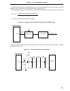
8.5 16-Bit Timer/Event Counter Operations
8.5.1 Interval timer operations
Setting the 16-bit timer mode control register (TMC0) and capture/compare control register 0 (CRC0) as shown
in Figure 8-10 allows operation as an interval timer. Interrupt requests are generated repeatedly using the count value
set in 16-bit capture/compare register 00 (CR00) beforehand as the interval.
When the count value of the 16-bit timer register (TM0) matches the value set to CR00, counting continues with
the TM0 value cleared to 0 and the interrupt request signal (INTTM00) is generated.
Count clock of the 16-bit timer/event counter can be selected with bits 4 to 6 (TCL04 to TCL06) of the timer clock
select register 0 (TCL0).
For the operation when the value of the compare register has been changed during timer count operation, refer
to section 8.6 (3) Operation after compare register change during timer count operation.
Figure 8-10. Control Register Settings for Interval Timer Operation
(a) 16-bit timer mode control register (TMC0)
(b) Capture/compare control register 0 (CRC0)
Remark 0/1 : Setting 0 or 1 allows another function to be used simultaneously with the interval timer. See
the description of the respective control registers for details.