


455
CHAPTER 19 SERIAL INTERFACE CHANNEL 2
(2) Communication operation
(a) Data format
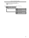
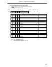
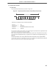
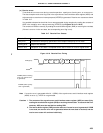
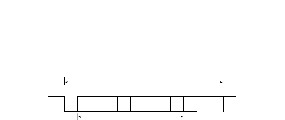
The transmit/receive data format is as shown in Figure 19-7.
Figure 19-7. Asynchronous Serial Interface Transmit/Receive Data Format
1 data frame is composed of each of the bits shown below.
• Start bits.................. 1 bit
• Character bits ......... 7 bits/8 bits
• Parity bits ................ Even parity/odd parity/0 parity/no parity
• Stop bit(s) ............... 1 bit/2 bits
The character bit length, parity selection, and stop bit length for each data frame is specified with the
asynchronous serial interface mode register (ASIM).
When 7 bits are selected as the number of character bits, only the lower 7 bits (bits 0 to 6) are valid; in
transmission the most significant bit (bit 7) is ignored, and in reception the most significant bit (bit 7) is
always "0".
The serial transmission rate is set by ASIM and the baud rate generator control register (BRGC).
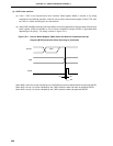
If a serial data receive error is generated, the receive error contents can be determined by reading the
status of the asynchronous serial interface status register (ASIS).
D0 D1 D2 D3 D4 D5 D6 D7
Parity
Bit
Stop Bit
Start
Bit
One Data Frame
Character Bits