


438
CHAPTER 19 SERIAL INTERFACE CHANNEL 2
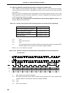
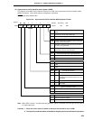
65432107
Symbol
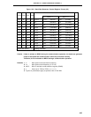
CSIM2 CSIE2 0 0 0 0
CSIM
22
CSCK 0
FF72H 00H R/W
Address After Reset R/W
CSCK
0
1
Serial Operating Mode Selection
UART mode
3-wire serial I/O mode
CSIM22
0
1
First Bit Specification
MSB
LSB
CSIE2
0
1
Operation Control in 3-wire Serial I/O Mode
Operation stopped
Operation enabled
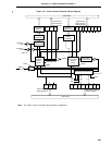
19.3 Serial Interface Channel 2 Control Registers
Serial interface channel 2 is controlled by the following four registers.
• Serial operating mode register 2 (CSIM2)
• Asynchronous serial interface mode register (ASIM)
• Asynchronous serial interface status register (ASIS)
• Baud rate generator control register (BRGC)
(1) Serial operating mode register 2 (CSIM2)
This register is set when serial interface channel 2 is used in the 3-wire serial I/O mode.
CSIM2 is set with a 1-bit or 8-bit memory manipulation instruction.
RESET input sets CSIM2 to 00H.
Figure 19-3. Serial Operating Mode Register 2 Format
Cautions 1. Ensure that bits 0 and 3 to 6 are set to 0.
2. When UART mode is selected, CSIM2 should be set to 00H.