


295
CHAPTER 16 SERIAL INTERFACE CHANNEL 0 (
µ
PD78058F SUBSERIES)
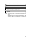
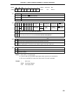
WUP
0
1
Wake-up Function Control
Note 1
Interrupt request signal generation with each serial transfer in any mode
Interrupt request signal generation when the address received after bus release (when CMDD = RELD = 1)
matches the slave address register (SVA) data in SBI mode
R/W
COI
0
1
Slave Address Comparison Result Flag
Note 2
Slave address register (SVA) not equal to serial I/O shift register 0 (SIO0) data
Slave address register (SVA) equal to serial I/O shift register 0 (SIO0) data
R
CSIE0
0
1
Serial Interface Channel 0 Operation Control
Note 3
Operation stopped
Operation enable
R/W
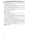
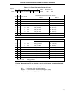
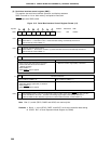
Figure 16-4. Serial Operating Mode Register 0 Format (2/2)
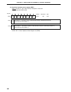
Notes 1. To use the wake-up function (WUP = 1), clear the bit 5 (SIC) of the interrupt timing specify register
(SINT) to 0.
2. When CSIE0 = 0, COI becomes 0.
3. In the SBI mode, the operation of serial interface channel 0 should be stopped (CSIE ← 0) after
clearing WUP to “0”. If WUP is not “0”, P25 is fixed at high level, and it is not possible to use it
as a normal port.