


243
CHAPTER 10 WATCH TIMER
0
7
TMC26
6
TMC25 TMC24
4
TMC23
3210
FF4AH
Address
TMC2
Symbol
TMC22 TMC21 TMC20
5
00H
After
Reset
R/W
R/W
0
1
TMC23
2
14
/f
W
(0.4 sec)
2
13
/f
W
(0.2 sec)
Watch Flag Set Time Selection
0
0
0
0
1
1
Other than above
0
0
1
1
0
0
0
1
0
1
0
1
TMC26 TMC25 TMC24
2
4
/f
W
(410 s)
2
5
/f
W
(819 s)
2
6
/f
W
(1.64 ms)
2
7
/f
W
(3.28 ms)
2
8
/f
W
(6.55 ms)
2
9
/f
W
(13.1 ms)
Setting prohibited
2
4
/f
W
(488 s)
2
5
/f
W
(977 s)
2
6
/f
W
(1.95 ms)
2
7
/f
W
(3.91 ms)
2
8
/f
W
(7.81 ms)
2
9
/f
W
(15.6 ms)
2
4
/f
W
(488 s)
2
5
/f
W
(977 s)
2
6
/f
W
(1.95 ms)
2
7
/f
W
(3.91 ms)
2
8
/f
W
(7.81 ms)
2
9
/f
W
(15.6 ms)
Prescaler Interval Time Selection
µ
µ
µ
µ
µ
µ
2
14
/f
W
(0.5 sec)
2
13
/f
W
(0.25 sec)
2
14
/f
W
(0.5 sec)
2
13
/f
W
(0.25 sec)
TMC22
0
1
Clear after operation stop
Operation enable
TMC21
0
1
Clear after operation stop
Operation enable
TMC20
0
1
Normal operating mode (flag set at f
W
/2
14
)
Fast feed operating mode (flag set at f
W
/2
5
)
Watch Operating Mode Selection
Prescaler Operation Control
5-Bit Counter Operation Control
f
XX
= 5.0 MHz Operation f
XX
= 4.19 MHz Operation f
XT
= 32.768 kHz Operation
f
XX
= 5.0 MHz Operation f
XX
= 4.19 MHz Operation f
XT
= 32.768 kHz Operation
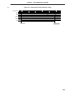
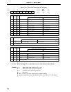
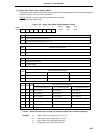
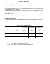
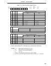
(2) Watch timer mode control register (TMC2)
This register sets the watch timer operating mode, watch flag set time and prescaler interval time and enables/
disables prescaler and 5-bit counter operations.
TMC2 is set with a 1-bit or 8-bit memory manipulation instruction.
RESET input sets TMC2 to 00H.
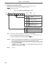
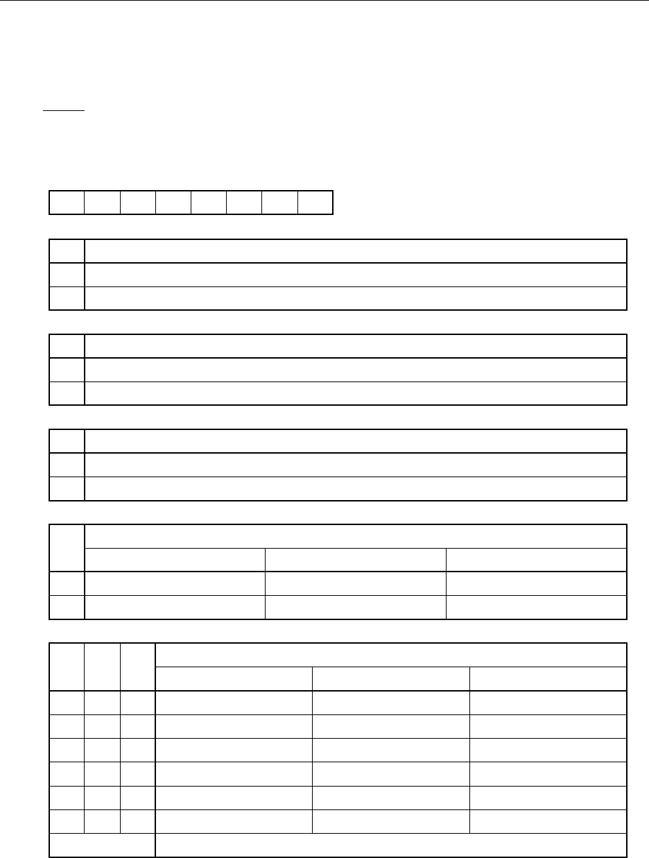
Figure 10-3. Watch Timer Mode Control Register Format
Caution When the watch timer is used, the prescaler should not be cleared frequently.
Remarks f
W : Watch timer clock frequency (fXX/2
7
or fXT)
fXX : Main system clock frequency (fX or fX/2)
f
X : Main system clock oscillation frequency
fXT : Subsystem clock oscillation frequency