AMD Geode™ LX Processors Data Book 45
4
GeodeLink™ Interface Unit 33234H
4.0GeodeLink™ Interface Unit
Many traditional architectures use buses to connect mod-
ules together, which usually requires unique addressing for
each register in every module. This requires that some kind
of house-keeping be done as new modules are designed
and new devices are created from the module set. Using
module select signals to create the unique addresses can
get cumbersome and requires that the module selects be
sourced from some centralized location.
To alleviate this issue, AMD developed an internal bus
architecture based on GeodeLink™ technology. The
GeodeLink architecture connects the internal modules of a
device using the data ports provided by GeodeLink Inter-
face Units (GLIUs). Using GLIUs, all internal module port
addresses are derived from the distinct port that the mod-
ule is connected to. In this way, a module’s Model Specific
Registers (MSRs) do not have unique addresses until a
device is defined. Also, as defined by the GeodeLink archi-
tecture, a module’s port address depends on the location of
the module sourcing the cycle, or source module (e.g.,
source module can be CPU Core, GLCP, and GLPCI; how-
ever, under normal operating conditions, accessing MSRs
is from the CPU Core).
4.1 MSR Set
The AMD Geode™ LX processor incorporates two GLIUs
into its device architecture. Except for the configuration
registers that are required for x86 compatibility, all internal
registers are accessed through a Model Specific Register
(MSR) set. MSRs have a 32-bit address space and a 64-bit
data space. The full 64-bit data space is always read or
written when accessed.
An MSR can be read using the RDMSR instruction, opcode
0F32h. During an MSR read, the contents of the particular
MSR, specified by the ECX register, are loaded into the
EDX:EAX registers. An MSR can be written using the
WRMSR instruction, opcode 0F30h. During an MSR write,
the contents of EDX:EAX are loaded into the MSR speci-
fied in the ECX register. The RDMSR and WRMSR instruc-
tions are privileged instructions.
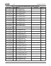
Table 4-1 shows the MSR port address to access the mod-
ules within the AMD Geode LX processor with the CPU
Core as the source module.
Table 4-1. MSR Addressing
Module Name GLIU Port
MSR Address
(Relative to CPU Core)
GeodeLink™ Interface Unit 0 (GLIU0) 0 0 1000xxxxh
GeodeLink Memory Controller (GLMC) 0 1 2000xxxxh
CPU Core (CPU Core) 0 3 0000xxxxh
Display Controller (DC) 0 4 8000xxxxh
Graphics Processor (GP) 0 5 A000xxxxh
GeodeLink Interface Unit 1 (GLIU1) 1 0 4000xxxxh
Video Processor (VP) 1 2 4800xxxxh
GeodeLink Control Processor (GLCP) 1 3 4C00xxxxh
GeodeLink PCI Bridge (GLPCI) 1 4 5000xxxxh
Video Input Port (VIP) 1 5 5400xxxxh
Security Block (SB) 1 6 5800xxxxh


